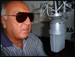
 I like the shades! |
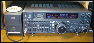
K6JRF's Page formerly W6FZC Yaesu FT2000 ESSB Audio Setup |

|
(New: May 13, 2017)
 I like the shades! |
K6JRF's Page formerly W6FZC Yaesu FT2000 ESSB Audio Setup |

|
|
Yagi Design Data A number of years ago, I gave a presentation to the San Diego DX Club for the work I had done on yagi design, my favorite pastime! It's in two (2) parts; the first a treatise on stacked yagi design that I actually did put up on my tower and the theoretical analysis that backs it up. It was a real learning experience and I've revived the report, scanned it and made a Word DOC file for you to download. I highly recommend that you do this BEFORE you decide to put up a stacked antenna system. The second part is the compilation of some more famous commercial yagis that I made in order to 'rank' the performance of these commercial yagis. Also did some analysis of some yagis in use by "big-guns"! I hope that you find it interesting. |
 The report is here
The picture shows the 20Mtr yagi stack in use during the late 80s on my US Tower MARB88MDP. The top antenna is 4el HyGain HG204BA yagi stacked with another HG204BA at 55ft level as shown in the sketch on PAGE 3. The picture shows a 4el yagi at 91ft with the lower one at 55ft, apx 46ft separation. This is NOT AN OPTIMUM STACKING distance but it was all I had. As you will see on PAGE 5 that the FG for the stacked-pair is 1dB greater than a single yagi! Also, the takeoff angle is 2 degrees HIGHER than the single yagi! And all the required stacking cable harness and extra expense for 1dB! You tell me if it's worth it? It should be obvious that to stack 20mtr yagis, the tower height should be 140ft or more! You can then place the upper yagi on the top (140') and the second yagi at, say, the 85-90ft level. Now there's no "penalty" since the wave angle and FG for the pair will be greater than just one yagi as it was for the 90ft tower. The advantage of 20M stacks is the high angle lobe that is a by-product of the low height and short-spacing. This produces produces an extremely stong "stateside" signal. Signal levels on a distant S-meter of 50-60dB over S9 are not unusual! The "owls" shown on the top 20M yagi and the 40M yagi were placed in an attempt to keep the birds off . . . but it didn't work! To keep birds off, you MUST prevent them from landing b/c once they do, they REMEMBER! |
|
Balun Measurements I decided to measure the performance of some more popular BALUNs that are in use. Starting on PAGE 16, the table shows the results of measurements made using the HP4191A RF Impedance Analyzer. It was instructive to measure the FREQUENCY response vs Impedance. As you see, one of the worst is the popular HyGain BN86. The best IMO, is the "choke" balun made famous by W2DU. Its impedance is well maintained from the 80Mtr band through the upper range of 10Mtr band. It's what you need to use! PAGE 17 shows the results of circuit analysis with various parameters varied and then analyzed with a fixed length of coax feedline = 80ft. PAGE 19 shows the equivalent ckt analysis of the "HAIRPIN" match system for inductive and capacitive matching. The Taper Hairpin Matching program cited on PAGE 20 is here. The program [version HP_V4.83] calculates the required taper WIDTH and LENGTH to match the feedpoint impedance. In case you get "lost", it can be downloaded here. |
Replace the 20M Yagi Stack The 20M yagi stack was replaced with a single 20M yagi made from a Create Design CL-20 4el yagi on a 30.5ft boom. Data
for the CD line of yagi antennas can be found here.
The 20M yagi stack was replaced with a single 20M yagi made from a Create Design CL-20 4el yagi on a 30.5ft boom. Data
for the CD line of yagi antennas can be found here.The reason I replaced the 20M stack with a single yagi is based on the data starting on PAGE 5. My final design consists of four (4) els on a 41 ft boom mounted at 91ft on the top section of the tower. The FG and FB is shown on PAGE 23. In summary, the FG = 10.3dBi w/ >35dB F/B at 14.190Mhz. Working our way down the tower shows the HyGain DB-1015 10M/15M yagi with 3els. It is basically stock. Next antenna down is the Create Design CD-78 80mtr dipole. It too was basically put up in a stock condition with the "high-power" coils. It's been in use for 40+ years!! Design info from CD is here. The next yagi down is the XM-240, 2el 40mtr beam by Cushcraft. Info can be found here. A nice, light weight yagi good for So Cal weather. The picture shows the tower cranked down to apx 40% of the full-up height for cable maintance. |
|
Yagi Compilation The report is here  The FG [Forward Gain], FB [Front-Back Ratio] and GW [Gain Bandwidth] are calculated using the actual
dimensions (including the element taper) to arrive a summary of each yagi's performance.
 - Gn Loss: the present FG of the yagi with the current dimensions and element spacing. This figure gives an idea of how much additional gain is THEORETICALLY available. I use the following in the yagi titles; - Just the yagi name means that it's the STOCK antenna. Results shown are for out-of-box dimensions. - NB = Narrow Band meaning the a portion of the band is selected. Results are for a portion of the band. - BB = Broad Band meaning the complete band is used. If there not enough space (limited to 8 characters), then it's abbreviated to "N" or "B". This report is a collection of some of the more popular yagis in use at the time including; - Cushcraft - page 2 - CD 20-4CD 4el stock - page 4 - 6 - CD CL20 4el longer boom - page 7 - 8 - DX SPC1 4el - 52' boom - page 10 - HyGain 204BA / 205BA - page 12 - 14 - HyGain 155BA - page 15 - 16 - HyGain 105BA - page 17 - W6FR 3el 20mtr - page 19 - W6XI 5el 10mtr - page 19 - W6CCP 7el 20mtr - page 20 Hope that you enjoy the yagi compilation. |
|
|