|
Hot Wire, Sequential Fuel Injection System: LH-SFI Module N3/1

Description and Operation
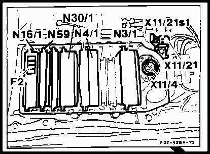
The LH-SFI module (N3/1) is located in the F23 module box and color coded GREEN. The
module is equipped with a memory that retains malfunctions codes even after the battery has been disconnected.
The LH-SFI ECU contains several programs and functions as described in the following:
- Voltage Supply (+12.5V)
- Starter circuit
- Engine temperature from coolant temperature sensor (B11/2)
- Intake air temperature from intake manifold temperature sensor (B17/7)
- Intake air mass from mass air sensor (B2/2)
- Various information from the controller area network (CAN)
- ABS/ASR information from ABS/ASR control module (N30/1)
- Air/fuel mixture from oxygen sensor (G3/2)
- ON signal from air injection
- ON signal for exhaust gas recirculation (EGR)
Control Functions
 During normal driving, the ECU use the input devices to regulate injection frequency and timing. The two most influencing
components are:
- Air mass sensor with hot wire (B2/2)
- Engine RPM signal (TN)
Warm-up Function
The start control provides for longer injection duration to enrich the mixture. The final air/fuel mixture is dependent on
the engine coolant temperature. Mixture enrichment stops when the engine is at operating temperature.
Acceleration Function
During acceleration a richer air/fuel mixture is provided to achieve maximum engine power. This will also keep combustion
heat and catalytic converter temperature at an acceptable level.
Deceleration Function
During de-acceleration, the fuel injectors are turned off (in all gears) if engine temperature is above 158 deg F. The
engine speeds for injections cut-off / restart vary from 8 injectors at 1400 rpm to 0 injectors at less than 600 rpm.
Max Engine RPM Function
At excess RPM, the fuel injectors are turned off to keep the engine from overreving. The momentary engine RPM limit is
6300 +/- 50. After 10 seconds, the LH control module limits the engine to 6000 +/- 50 RPM.
Max Speed Function
The maximum vehicle speed is limited to 130 mph. If this speed is exceeded, the air/fuel mixture is leaned out and the
camshaft timing is advanced.
Self Adjusting Function
The ECU is adaptive to the changing engine operating parameters (wear and contamination of parts). It will adjust its
calculations according to assimilated input conditions. Whenever the vehicle is started or driven, the ECU will use the
value it has learned from the previous driving period.
Oxygen Sensor Function
The oxygen sensor (G3/2) operates in a similar fashion. It senses if the fuel mixture is rich or lean and the ECU adjusts
the oxygen sensor control accordingly. The self-regulating function keep the air/fuel mixture at a constant midpoint.
Therefore the need to adjust the CO content is eliminated.
Fuel Shut-Off Function
If due to a malfunction, the throttle valve opens further than the position called for by the accelerator pedal (cruise
control not in operation), the LH-SFI control module receives a signal and goes into a "limp home mode". This
pre-programmed mode will set the fuel injection frequency (opening duration) so the engine can't exceed 1100 RPM and the
vehicle can be slowly driven to the repair shop.
Diagnostic Function
If the LH-SFI control module detects a specific fault more than four (4) sequential times (ignition switched ON and OFF), a
fault code is stored in the module's memory. Only malfunctions which prevent/severely influence starting or operating of
the fuel injection system are immediately stored in the fault memory.
On California models, a "CHECK ENGINE" light will inform the operator of an emission related problem. It
illuminates when a certain malfunction in the engine management system is detected. The operator should bring the vehicle
to the repair shop as soon as possible.
Malfunctions which occur while starting or with the engine running are recorded by a malfunction counter. Malfunctions are
assigned a specific value according to the severity. For example, hot wire mass air flow (MAF) sensor is '128'. The coolant
temperature sensor (ECT) is '32'. The malfunction counter counts in stages up to a threshold value of 255. After reaching
the value of 128, intermittent malfunctions are stored into memory after switching off the ignition. Malfunctions which
affect engine operation (greater than or equal to 128) are immediately stored into diagnostic trouble code (DTC) memory by
the malfunction counter after switching off the ignition.
If a malfunction is no longer present during a subsequent engine start or engine operation, the total value recorded by the
malfunction counter is reduced by one (1) every time the engine is switched off. This procedure repeats itself until the
malfunction counter is cleared.
The malfunction memory can ONLY be accessed via the diagnostic connector (X11/4). The malfunction memory is not erased when
the battery is disconnected.
Malfunctions in the following areas are stored immediately:
- Cam position sensor (CMP)
- Hot wire MAF sensor
- Injectors
A malfunction in the following is stored after two (2) trips:
- Speed signal (TN)
Fault Table, DTC Readout, LH-SFI Module (N3/1)
Socket 1: Black (Ground)
Socket 3: Red (+12.5V)
Socket 4: Yellow (Pin for LH-SFI DTC readout)
| DTC Readout |
Possible Cause |
| 1 |
No Faults in System |
| 2 |
ECT sensor (B11/2) sensor circuit 1, open/short circuit |
| 3 |
ECT sensor (B11/2) sensor circuit 2, open/short circuit |
| 4 |
Voltage at hot wire MAF sensor (B2/2) insufficient or too high, or open circuit in ground wire at hot wire MAF sensor |
| 5 |
Not used |
| 6 |
Not used |
| 7 |
TN-signal (rpm signal) incorrect or open/short circuit |
| 8 |
CMP sensor (L5/1), open/short circuit |
| 9 |
Starter signal (circuit 50) missing, open/short circuit |
| 10 |
CTP (idle) recognition from EA/CC/ISC control module (N4/1), short circuit |
| 11 |
Secondary air injection system, open/short circuit |
| 12 |
Burn-off control for hot wire MAF sensor, open/short circuit |
| 13 |
IAT sensor (B17/7), open/short circuit |
| 14 |
Not used |
| 15 |
Not used |
| 16 |
EGR switchover valve (Y27), open/short circuit |
| 17 |
No CAN data transmission with EA/CC/ISC control module (N4/1) or N4/3) |
| 18 |
No CAN data transmission with DI control module (N1/3) |
| 19 |
Not used |
| 20 |
No CAN data transmission with LH-SFI control module (N3/1) |
| 21 |
O2S 1 (before TWC) (G3/2), open/short circuit |
| 22 |
O2S 1 heater, open/short circuit |
| 23 |
Purge control valve (Y68/1), open/short circuit |
| 24 |
Left adjustable camshaft timing solenoid (Y49/1), open/short circuit |
| 25 |
Right adjustable camshaft timing solenoid (Y49/2), open/short circuit |
| 26 |
Upshift delay switchover valve (Y3/3), open/short circuit |
| 27 |
Injectors (Y62), open/short circuit |
| 28 |
LH-SFI control module coding, open circuit |
| 29 |
1GR start relay module (K29/1), open/short circuit |
|


 During normal driving, the ECU use the input devices to regulate injection frequency and timing. The two most influencing
components are: