|
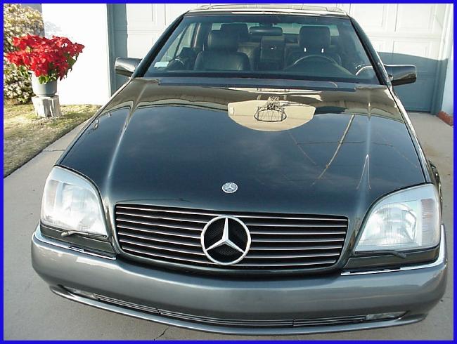
K6JRF's Page formerly W6FZC My Mercedes Benz S500 Coupe |

|
Analyze and Troubleshoot "Check Engine" MIL and Electronic Control Units (ECU)!
|
Engine Management Systems
The system uses three (3) interconnected Electronic Control Units (ECU); one controlling the fuel injection, one controlling the ignition system and finally one controlling the electronic accelerator system. All three systems have self-diagnostics and fault code storage. All faults can be accessed through the 38 pin diagnostic socket, X11/4 or the push button with LED (X11/21s1). The self-diagnostics is performed by the Diag Module (N59). The module constantly monitors engine performance by comparing its programming window with the values it receives via the Controller Area Network (CAN). When a programming parameter has been exceeded, a retrievable fault code is stored. If the Diag Module detects a serious fault code in the engine control system, it activates the 'CHECK ENGINE' light. By extracting the fault codes via the X11/4 socket or PB/LED, the faulty component can be identified and then tested further. Fuel Injection System The LH fuel injection system is based on the Bosch multi-port fuel injections system with mass airflow sensor (LH-Jetronic). This ECU uses electrical inputs from various devices and sensors to calculate engine load and condition. With this information, it adjusts the injection duration and timing to provide optimum air/fuel mixture for performance, drivability and emissions compliance. Adaptive Memory Time and mileage affect the operation of both the injection and the idle control systems. To compensate for wear and deposit accumulation, the LH system modifies its basic programming to provide for efficient operation under all driving conditions. If the system determines that it must modify it basic programming beyond the preset window limit, a fault code is stored in the self-diagnostic memory. Limp Home Operation If the ECU determines that the mass air flow signal is incorrect or missing, the system enters a preset 'limp-home' mode. In this mode, preset injection duration is operational such that the car may be driven to an MB shop for repair. Ignition System The ignition system is based on the electrically controlled Bosch system with knock control. The ECU uses electrical input signals from various devices and sensors to calculate the engine temperature, load and speed. With this information, the ECU adjusts the ignition timing to provide optimum performance, economy and emissions. Electronic Accelerator System This ECU is equipped with an electronically controlled accelerator pedal/throttle plate. The Electronic Accelerator (N4/1) controls the idle speed. This system keeps the engine within a constant RPM when at idle. The system compensates for cold engine, high engine load or other influencing factors. Testing the Engine System To read and analyze the DTC, make sure the ignition key is set to the full 'ON' position. All warning lights should be on. To recall and reset CHECK ENGINE light codes on vehicles that use LH or HFM type fuel injection, the Diagnostics Module (DM) must be read. The faults must be cleared from the DM to shut off the CHECK ENGINE light on these vehicles. On vehicles with HFM type fuel injection, after checking for HFM fault codes, also check the EA/IC/ISC control unit for fault codes. On vehicles with LH type fuel injection, after checking for LH fault codes, also check the EA/CC/ISC and Distributor Ignition (DI) control unit for fault codes. Vehicles that use ME fuel injection do NOT have separate DM, EA/CC/ISC or DI control units. These functions have been integrated into the ME control unit. Attempting to access these control units will generate an error message. To verify that a vehicle is equipped with a particular engine system, refer to the MB Engine Management Systems Chart below. Of course, the use of a scanner is required to be able to read all codes from each ECU. Climate Systems Many vehicles have climate control systems that can be accessed through the display panel in the passenger compartment. By simply setting the TEMP control wheels and pushing the AUTO function, the complete status of the AC can be determined. ABS and ASR Systems Anytime the scanner tool access's the ABS control unit, the ABS warning lamp will illuminate. The light will stay on until the scanner tool is disconnected and the ignition key is cycled. Online Auto Repair by ALLDATA DIY The very popular CD-ROM has been discontinued and replaced with an online yearly subscription to ALLDATA DIY for $24.95 that is renewable for $14.95. Since I haven't tried this service I can't recommend it. Currently, information is available for model years 1982 to 2000. 2001 model year information is scheduled to be released in June/July of 2002. The information available is summarized here: • Factory Recall and Technical Service Bulletins (TSB) • Information that addresses safety, reliability, performance and comfort related problems with your car • Special warranty provisions and extensions. • Fixes for common problems and updated factory repair procedures • Illustrated Diagnosis and Repair Procedures • OEM Part Numbers • Diagnostic Charts and Trouble Codes • Component Locations and Diagrams • Factory Maintenance Schedules For more info, check out this link: ALLDATA DIY.
|
|
Send me |

