|
NOTE 7
This report details modifications to the FT1000D FAN circuitry to increase the radio's cooling
while lowering the noise. This is accomplished by adding two (2) resistors.
The FT1000's fan is a source of noise for me due to the high gain of the audio processing equipment. This makes the mic
very susceptible to noise pickup especially when the fan switches to HIGH cooling mode. The high frequency (400 - 700hz)
whine seems to 'propagate' right into the output audio. When in LOW speed, it cools the complete radio as well as being
almost noiseless. This modification keeps the fan on LOW speed continuously and changes the high speed rpm when it kicks
in.
LOW Speed Operation:
The picture below shows the schematic (Rload simulates the fan current load) and circuit simulation results of the fan
control circuit. A short theory of operation follows: thermistor TH7602, located on the HEATSINK's
right side, controls the input to an op amp Q7611-2 such that when cold, the output is HIGH (+8V). The cold resistance is
around 3.7K ohms and the voltage on pin 5 (+ in) is apx 5.5 volts. The voltage on pin 6 (- in) is fixed at 4.5 volts. Thus,
the output of op amp Q7611-1 is LOW (-8V) which cuts off the driver transistor, Q7621.
As the radio warms, thermistor TH7602 heats up and drops in resistance, thus dropping the voltage on pin 5. When the voltage
drops below the threshold point (4.5V) and the output switches LOW (-8V). This is inverted in op amp Q7611-1 to +8V which
turns the FAN on LOW speed by turning on transistor Q7621 providing a path for current flow from J7607 FAN2 to FAN1. The fan
is tied to +30V through R7640, 27 ohms. Transistor Q7612, that is AC coupled (220uf), provides a current 'kick' to the fan to
insure that it starts.
HIGH Speed Operation:
The fans switches to high speed when J7608, pin 2 (TG standing for Thermal Guard) drops to ground potential. Referring to the
FT1000 SERVICE MANUAL, page 7-125 shows the connector. This connects to the PA UNIT Board, page 7-87. In bottom corner, TG
unit TS7001 applies a GROUND to effectively short around R7650 (120 ohm) resistor which allows the fan to go into high speed.
At this speed it is really noisy! The sensor is manufactured by TOKIN (PN: OHD3-60M). It appears to be a temperature
sensitive device with a contact closure that provides a 'ground'.
|
You should clean and lubricate the fan as part of this modification.
Although not mandatory, it's a good idea because after years of use, albeit intermittently, you'll find lots of dust!
To remove the fan assembly which is 'buried' beneath the Low Pass Filter (LPF) Unit, do the following:
1) After removing the top and bottom covers, remove the LPF Unit by removing its cover, the four (4) indicated screws (see pic)
holding it to the main chassis and disconnect all RF and Molex connectors.
2) Remove the PS distribution unit on the left side behind the power transformer by removing the indicated screw on the floor
of the chassis and all Molex style plug-in connectors
3) Remove the screw on the back panel next to the IEC (AC line input) connector. Also remove the sheet metal screw on the back
panel of the PS distribution unit that secures the fan housing.
4) Remove the red/black wire connector that plugs into the PS Board. This provides power to the fan and gently reroute any
cable harness wires in the way.
5) Lift out the metal bracket that supports the LPF Unit.
6) The fan can now be removed by gently working it out from the floor of the main chassis. It floats on rubber feet.
7) Completely disassemble the fan and clean thoroughly. Lubricate the bearing surfaces with a light oil such as Radio Shack
'LUBRICATOR' pn 64-2301A. It contains Teflon and further quiets any rotational fan noise.
8) Reassemble by reversing the above steps.
You will find that the fan is very quiet now. Since the fan will now be running continuously, this preventive maintenance
procedure will pay dividends later on.
|
Modifications:
As with all of my modifications, you should have the FT1000 Service Manual. The following mod is accomplished with just two
resistors. Here's the compete instructions:
1) Remove the TOP COVER (8 screws) and the POWER AMP shroud (6 screws) on the back of the radio.
2) Locate thermistor TH7602 where it solders into the PS UNIT Board.
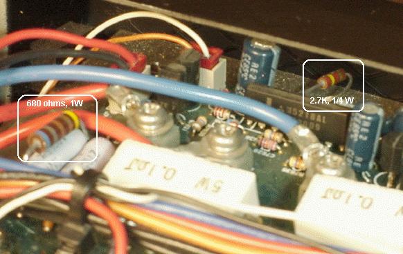
3) Solder a 2.7K, 1/4W resistor across the terminals of the thermistor.
4) Locate the PA UNIT Board. Remove connector J7007 (marked J07).
5) The two wires are white (hot, TG signal) and brown (ground). Cut the WHITE wire about 2 inches from the end and solder a
47 ohm, 3W wirewound resistor in series with the connection. Placed shrink tubing over the resistor and shrink until
tight.
6) Plug connector into J07. Replace shroud and top cover.
OPTIONAL: The fan speed is controlled by R7650 (120 ohms). You can change this resistor to say 75 - 100 ohms by
paralleling with another resistor (at least 1 watt) to increase the low speed cooling rpm. I used 680 ohm, 1 watt
resistor. The parallel combination is 102 ohms. This increases the fan rpm by 15% which increases the cooling
but does not generate excessive fan noise.
The fan will now run continuously on low speed when the radio is powered up. This keeps the radio remarkably cool. Even after
6 hours, the top, sides and back are very cool to the touch. If the PA output stage gets hot enough, the FAN will kick into
high speed mode but at reduced rpm due to the 47 ohm resistor. This will take a little longer to cool down the PA since the
rpm is about 60% of the original. However, the noise is quite low and airflow is adequate.
|
