
|
K6JRF's Page formerly W6FZC My Mercedes Benz S500 Coupe |
|
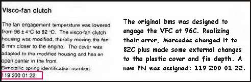
Analyze and Troubleshoot "Check Engine" MIL and Electronic Control Units (ECU)!
|
Testing of Sachs Viscous Fan Clutch 2100 013 032
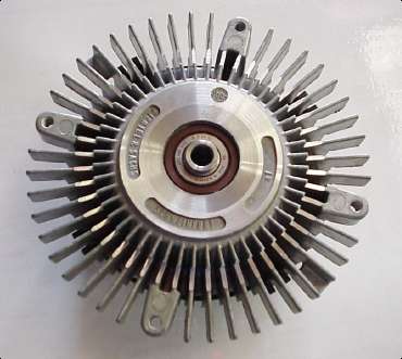
Description
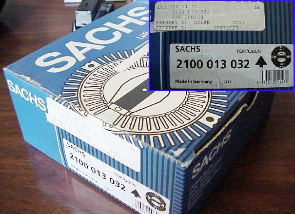
The box is bright dark blue with the labelling on the side that shows the Sachs PN: 2100 013 032 and the MB PN: 119 200 01 22. Front and Back Side Views
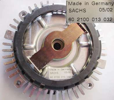
The new bms and the removal of the plastic 'cage' serve as an insulation effecting resulting in less heat transfer to the bms. This the removal of the center portion is probably worthwhile. The bolt hole pattern is compatible with the 'S' class cars, so it could be used there although it is not specifically called out for use with that car. More height differences can be seen in further down the page. VFC Fins, Height and Commonality 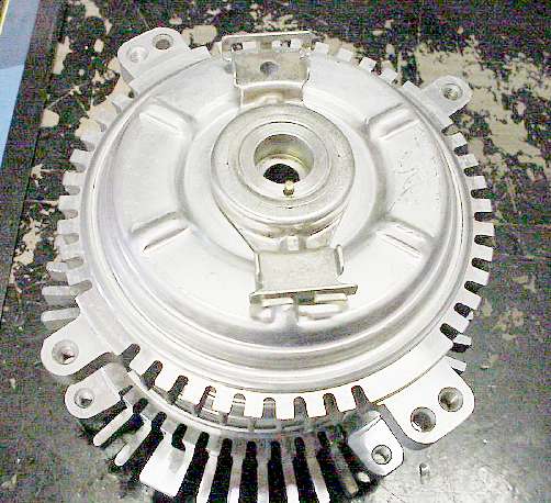
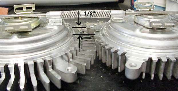
The picture shows the contrast of the re-designed fin lengths, and bolt pattern commonality between the old (on top) and new (underneath) part. The fins have been extended apx 1" greater than the old part possibly to increase the thermal inertia. but the benefit, if any, is not readily apparent! This part as stated is intended for the 'E' class (W124) car including the 500E/E500. Operation is not specifically mentioned for W140 and C140 cars. But inspecting the bolt patterns (4 holes), it could be use on the W140 cars. In addition, the part number is MB compatible with 140 autos: 119 200 01 22. Both VFCs are the same 'depth' as shown by the straightedge tool resting on top, but fins have cut back about 0.5" on the new part which results in moving the fan closer to the engine. This effectively moves the fan blades further out of the fan shroud, so the result would be less air drawn through the radiator. Therefore, more 'heat' (air-temperature) will be available to heat the bms. But, the fallacy, is that the engine temperature will rise even further until the bms bends enough to cause the vfc to lock.
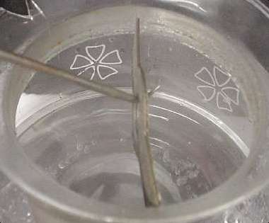
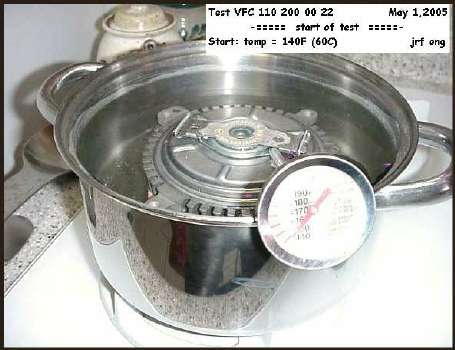
BMS Heat Test
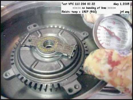
BMS Test Comments The slight differences in the fin design (allowing the fan to be further away from the radiator) will not improve the operation of the unit, in my opinion. Also the bimetallic strips for both units are identical, they will both respond to heat in the same way (see the section below that "proves" that statement). So taken in total, this unit will operate the same as the older part. The list price is $595.00! Water vs Air Tests There seems to be a lot of confusion about testing a bms in water vs air. In short, there is absolutely no difference between the two! They both are mediums that we encounter every day. The confusion seems that the "air-flow" is equated with "air-temperature". For example, here's an excerpt from a post on the VFC and bms. " . . if the bms can not detect changes in the ambient temperatures properly, because of inadequate air flow around it, . . . it does not mean that there is something wrong with its design. The solution would be to increase the air flow around the bms to allow it to react quicker to changes in temperature. . ". As you can see, the poster incorrectly thinks that the bms can be made to react quicker by increasing the air-flow. You can have 40 cfm of air-flow whose (air) temperature is 50C. So air-flow is not the answer. But if he said ". . increase the air-temperature around the bms . . ", then he would be correct. Simply stated, it is AIR-TEMPERATURE that the bms responds to, not air-flow. When we test in water, note that there is almost ZERO water-flow (other than that by convection). But there's a 'lot' of water temperature, homogeneous water temperature surrounding the bms. It's water-temperature that the bms responds to. Very simple really. But those who are not technically inclined are always prone to this common error. As you have figured out, water-flow is the equivalent to air-flow. So for our subject bms being tested in water or air, it will respond exactly the same in either medium. Of course, it's much easier to test in water since we can easily control the environment. Testing in air is much more difficult since it's difficult to simultaneously heat and contain a volume of air as we can with water. Test of Complete VFC w/ BMS I decided to test one of the VFC assy that I been using to see if mounting the bms into the VFC frame would cause to bend at a different temperature than just the bms itself. You have just seen the test of the a brand new Sachs VFC (119 200 01 22) bms alone in water. The bms bent at 98-100C enough so that the clutch would engage and lock up the fan. Possibly, there could be a compounding effect that would cause the bms to bend at a lower temperature than it would just by itself. From the theoretical standpoint, that is impossible since a bms is a 'closed system' and as such it must respond to temperature by bending based on the metallic expansion of each metal used in the amalgam. It will always respond the same to applied temperature based on the coefficient of expansion (COE) of each metal in the amalgam. It must follow the thermal expansion laws that govern it. The VFC frame could be an influencing factor in that if it were a 'bms' of the right metals and if the metal amalgam was correctly fabricated, it could cause the primary bms to effectively bend at a lower temperature than it would. So with that in mind, I tested the complete VFC assy in water. You should note that the water test is more likely to induce the bms to bend because the water temperature is more homogeneous than it can be when the VFC assy is mounted in the car. The air temp forced from the input side will always tend to lower the temperature seen at the VFC assy. The two pictures below show the results of the test. One taken at the start; water at 140F (60C) and the final at 194C (90C). My assistant (the 'boss') holds the thermometer in the second picture. As suspected, the bms did not BEND at 90C. This proves that the frame that holds the bms is not another bms in itself and the bms 'obeys' its COE for the metals involved. Also the findings were the same as my stand alone 'bms' water test detailed in the previous section. |
|
|
|
|
|
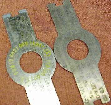
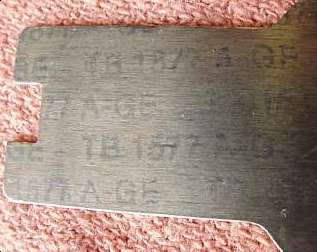
It shows that for this VFC assy, despite incorrect contrary any claims made by others, that this VFC does not operate
until 100C, meaning that the coolant in the radiator must be AT LEAST 110C (but probably more) before 100C can be reflected
into the bms to cause it bend enough to engage the clutch. Furthermore, any bms that has the markings of the bms tested, you
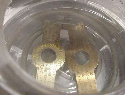
can be assured that it will not bend until the temperature is around 100C. The markings are "TB 1577A -GE". It's also
imprinted with the MB PN 119 200 00 22. Overall Conclusions In summary, it is now apparent that: 1) VFCs with PN 119 200 00 22 do NOT lock up until 100C at the bms, 2) VFCs with PN 119 200 01 22 do NOT lock up until 100C at the bms, 3) The replacement VFC, 119 200 02 22 also made with the "TB 1577A -GE" will not lock up until 100C at the bms. The bottom line conclusion is "ALL VFC assys made with the bms marked as "TB 1577A -GE" will NOT lock up until 100C at the bms. So the VFC modification described in Menu #20, will give superior cooling than this new unit and it's very cost-effective. |
|
Send me |