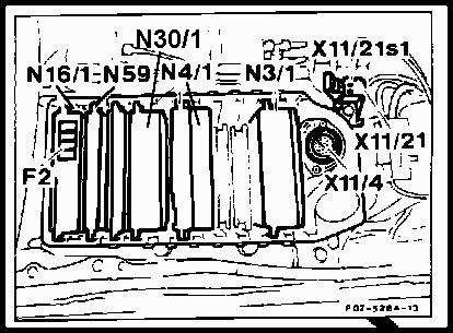
Fault Table, DTC Readout, Diagnostic Module (N59)
Socket 1: Black (Ground)
Socket 3: Red (+12.5V)
Socket 19: Yellow (Pin for DM DTC readout)
| DTC Readout |
Possible Cause |
Remedy |
| 1 |
No Faults in System |
- |
| 2 |
Heated oxygen sensor inoperative |
Test LH-SFI unit |
| 3 |
Lambda control inoperative |
Test LH-SFI unit |
| 4 |
Air injection inoperative |
Test LH-SFI unit |
| 5 |
Exhaust gas recirculation inoperative |
Test LH-SFI unit |
| 6 |
Idle speed control inoperative |
Test electronic accelerator |
| 7 |
Ignition system defective |
Test distributor igntion system |
| 8 |
Engine coolant temperature sensor, open/short |
Test LH-SFI unit |
| 9 |
Intake air temperature sensor, open/short |
Test LH-SFI unit |
| 10 |
Voltage at mass air flow sensor too high/low |
Test LH-SFI unit |
| 11 |
TN-signal (rpm) at LH-SFI control module (N3/1) defective |
Test LH-SFI unit |
| 12 |
Heated oxygen sensor heater, open/short circuit |
Test LH-SFI unit |
| 13 |
Camshaft position sensor signal of ignition control module (N1/3) defective |
Test LH-SFI unit |
| 14 |
Intake manifold pressure at start in N1/3 too low/high |
Test LH-SFI unit |
| 15 |
Wide open throttle information defective |
Test LH-SFI unit |
| 16 |
Closed throttle position information defective |
Test electronic accelerator |
| 17 |
Data exchange malfunction between individual control modules |
Test DM Step: 7.0 |
| 18 |
Adjustable camshaft timing solenoid, open/short circuit |
Test LH-SFI unit |
| 19 |
Fuel injectors open/short or self-adaptation in LH-SFI control module (N3/1) at limit |
Test LH-SFI unit and reset adaptation to mean value |
| 20 |
Speed signal not present |
Test electronic accelerator |
| 21 |
Purge switchover valve, open/short circuit |
Test LH-SFI unit |
| 22 |
Camshaft position sensor signal defective |
Test distributor system |
| 23 |
Intake manifold pressure in N1/3 with engine running too high/low |
Vacuum supply to N1/3; Test distributor ignition system |
| 24 |
Start ring gear segments and/or crankshaft position sensor defective |
Test distributor system |
| 25 |
Knock sensors or ignition control module defective |
Test distributor system |
| 26 |
Upshift delay 1 to 2 (model 123.034) , 2 to 3 (all models) |
Test LH-SFI unit |
| 27 |
Engine coolant temperature sensor deviation between sensor ckt 1 and sensor ckt 2 |
Test LH-SFI unit |
| 28 |
Engine coolant temperature sensor (coolant temperature change monitor |
Test LH-SFI unit |