|
Anti-Theft Alarm (ATA) System
Description, Operation and Location
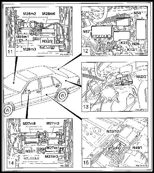
The Anti-Theft Alarm (ATA) system is made up of the following main components:
- ATA control module, N26
- Left front ESA control module w/ memory, N32/1
- Right front ESA control module w/ memory, N32/2
- RHR control module, N32/12
- Speed Sensitive Power Steering (SPS) control module, N49/1
- Remote Control (RCL) module, N54
- Convenience Features (CF) control module, N57
- Fuel Pump (FP) relay, K27
Fault Table, DTC Readout, SRS Control module (N2/2)
Socket 1: Black (ground)
Socket 3: Red (12V)
Socket 23: Yellow (ATA output)
| DTC |
Possible Cause |
| 1 |
No faults in system |
| 2 |
Alarm activated by trunk sensor circuit |
| 3 |
Alarm activated by engine hood circuit |
| 5 |
Alarm activated by rear door circuit |
| 6 |
Alarm activated by front door circuit |
| 10 |
Alarm activated by radio circuit |
| 12 |
Alarm activated by ignition circuit |
| 14 |
Alarm activated by brake circuit |
| 19 |
ATA Control module (N26) defective |
| 20 |
No ground connection, left front door actuator |
|