|
K6JRF's Page formerly W6FZC Yagi Design Techniques |
|
This section integrates the previous LG203BA construction plus adding a 40M dipole on the
same boom. The design used both Yagi Optimizer [YO] and Antenna Optimizer [AO] software to set lengths
of each antenna. This started with an email from Steve VK6VZ asking about adding a "moxon" 40M yagi interlaced with my extended boom LG203BA. After finding out what a "moxon" does, it became apparent that it would be difficult if not impossible. But there are some great alternatives and that's what this is about! In the 2nd update, the new SteppIR "UrbanBeam" wet my interest so some quick simulations where done. The results appear to be fantastic . . 6.5DBi F/G, 25+dB F/B ratio . . . all on a 10ft boom!! This info is in the 2nd Menu item. |
|
Quick Select Menu Select the desired analysis section here. - 3el 20M yagi + 40M -Full Size 40M DP. . . click here 3/21/19 - 2el 20M yagi + Cushcraft D40 Reflector. . . click here * D40 is a Cushcraft D40 model 40mtr shortened dipole |
|
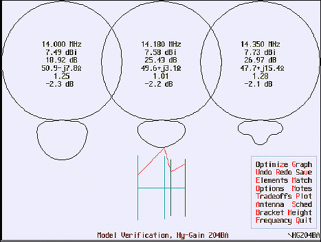
The OWA explanation: The Optimized Wideband Antenna (OWA) is antenna feed-point matching method developed by WA3FET that provides an increased feed point impedance while widening the VSWR bandwidth. The OWA is implemented in a yagi by moving the first director very close in front of the driven element. The only negative aspect of OWA yagis is that they give up a slight amount of forward gain (typically less than .5dB) from a conventional yagi. This small degradation is impossible to notice in operation and is well worth the simplicity of direct feed and the excellent bandwidth. Analyzing the "OWA" method; O = optimized . . . this word causes difficulties; optimized means only ONE parameter is "peaked", not all! W = wideband . . . implies complete band operation. Nothing wrong with that; A = antenna . . . dipole, yagi, quad, etc. No problem here. So the use of the term "optimized" is a problem! What does "OWA" method actually accomplish . . by moving the director closer to the driven element, the feed-point impedance is raised which reduces the F/G and reduces the SWR thereby increasing the operating bandwidth. That, friends as stated, is a "method" or a "technique" and results state that this method will make an optimized wideband antenna. The problem is that the optimization process only peaks ONE parameter at the expense of the others. The word "optimize" by definition means to make as perfect, effective, or functional as possible. Does performing the OWA method result in the best F/G and the best F/B and the best BW? The answer is NO! Performing this "method" results in a peaking of one parameter and compromise for the remaining parameters. This is far from the BEST, most favorable, ideal or perfect. So the OWA method can't be the BEST for all parameters! If I happen to want more F/G, the OWA method will not provide that. So performing the "OWA" method does NOT result in the BEST that can be done. However, the authors use the term optimize which implies to the reader that the antenna is now the best it can be when actually, it is less than it was before! Here's an example - - the HG204BA yagi features four (4) elements on a 26ft boom. The 'graphical' summary on the left shows what it does "out-of-the-box". Next to it on the right is the OWA technique to transform the yagi. 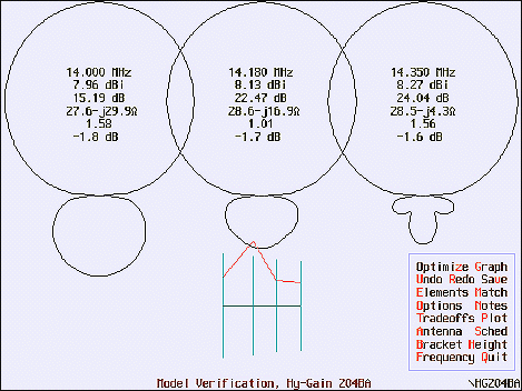
|
|
The stock 204BA meets a lot of users needs; good F/G, good F/B ratio with reasonable SWR across the complete 20M band.
Could that be called "the best"? If any version of this yagi could be called the best, this is it! There is absolutely
NOTHING wrong w/ that yagi as is. For MOST Hams, this yagi provides the
overall best in F/G, F/B and SWR that can be had for that boom length. And you
certainly can operate over the full 20M band w/o any SWR problems! By applying the OWA method/technique, the antenna is modified to loose some F/G while lowering the overall SWR (1.5:1 vs 1.2:1 is nothing to write home about). The main difference is that you can now use a direct 50 ohm coax feed. That is not necessarily an advantage b/c a balun is still required as it was before the OWA method. The only thing that has changed is the possible elimination of the "match" (hairpin for the HG204BA). Is this yagi now "better" than stock HG204BA? I don't think so! Actually the yagi's specs have been degraded but now some can now call this an OWA. A change s/b made to the "name"* to better define what was done to modify the antenna and remove the ambiguity using the word "optimized". This removes the mis-understanding with most Hams who think the antenna is now the "best" it can be b/c it was "optimized"!!! * A more appropriate term is . . . . Comprehensive Wideband Matching - CWM . . this much better describes what's going on. You loose F/G for the sake of operating bandwidth by changing feed-point impedance as the result of moving the director closer to the driven element. The resulting antenna is not OPTIMIZED for all parameters. |
|
Simulation vs Real World
This is good time to point out that there may differences from the simulation results vs what you put up in
the real world. Sometimes they are not the same. You should be prepared for this consequence. |
|
Background The Moxon [L. Moxon - G6XN] yagi peaked my interest and when a AO compatible file was located, the AO analysis showed how well it performs. The Word compatible file is here. Download it to see its amazing performance. Now that this the moxon antenna has peaked my interest, I reviewed my previous work to "refresh" what I used-to-know-but-long-since-forgotten!! Typically, I've had poor results trying to add a lower frequency, say 40mtrs to a 20 mtr yagi. As is well known, the higher frequency antenna normally suffers from this action. I've abandoned this approach a long time ago. But adding a single element, such as a 40M dipole, will work if it's added BEHIND the reflector. AO simulations confirmed that nicely. The bad news is that precious boom length is lost with this approach due to the spacing required. As a result, the 20M performance is reduced proportionally. Of course, the COG is upset and with the large weight load at the end of the boom. This means a truss is mandatory. To try to balance the "load", I found that when the 40M dipole is placed between the 20M driven and director, the 20M yagi becomes useless b/c its feed impedance, F/G and F/B ratio are destroyed and, to boot, it's difficult to match! But I found that you can place the 40M DP between the reflector and driven element and actually gain performance depending on the placement. The closer it is to the driven element the more interaction causing a better F/B ratio than if it was placed closer to the reflector end of the boom. And, since there's no boom lost, the director spacing can be increased to give more F/G. Finally, the 40M dipole is closer to the beam's center of gravity, mounting the antenna will be easier. However, the boom will probably need a "truss" to prevent excessive sag. So that's what inspired this effort. Extended LJ203BA + 40M Dipole Using the Extended LJ203BA (203BAE) as the starting point, a AO run shows the following: Impedance 13.2 - j 20.8 ohms Wire Losses 0.04 dB Efficiency 99.0% At 14.0 deg Elevation: F/G 13.11 dBi F/B 28.04 dB B/W 64 degs Extended LJ203BA + 40M DP - 20 Meter Performance 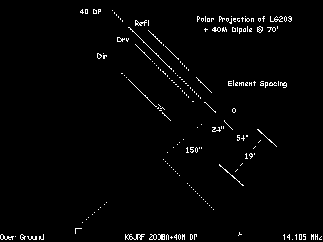 The projection plot shows the elements of each antenna and their placement on the boom. Shown are the 20M yagi and
the interlaced 40M dipole between the REFL and DRIVEN element. This is the "good" news since it now possible to have
an interlaced antenna without significant sacrifice of either antenna's performance. This IS good news!
The projection plot shows the elements of each antenna and their placement on the boom. Shown are the 20M yagi and
the interlaced 40M dipole between the REFL and DRIVEN element. This is the "good" news since it now possible to have
an interlaced antenna without significant sacrifice of either antenna's performance. This IS good news!The element separation is as shown: 20M Refl to 40M DP = 54" 40M DP to Drv ele = 24" Drv ele to Dir = 150" Total boom length = 228" AO analysis done "over ground" at 70ft. |
|
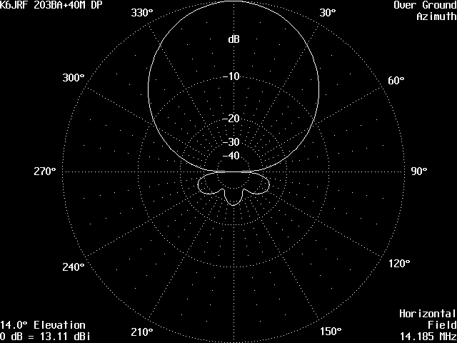 The azimuth plot shows a clean pattern with 64 deg pattern. F/B ratio is exceptional good - apx 28dB.
|
|
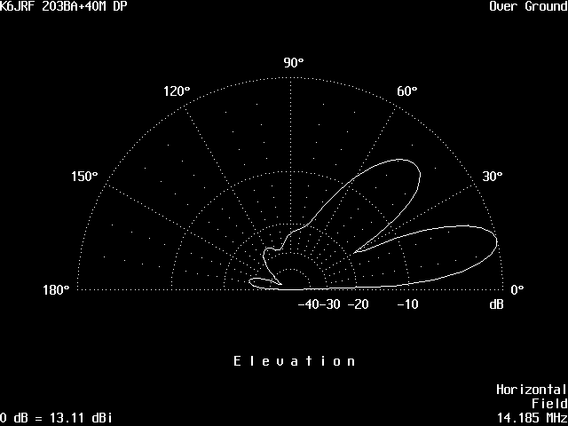 The elevation plot shows a clean forward projection pattern with 14 deg takeoff (DX) and 44 deg high-angle pattern. Again
the F/B ratio is exceptionally good - apx 28dB.
|
|
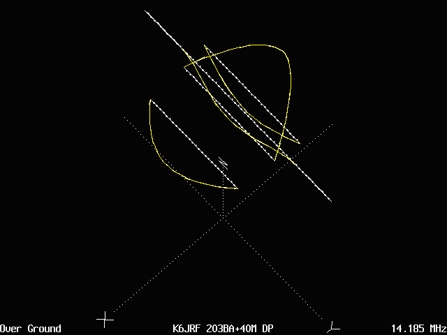 The current vectors (yellow) are shown for 20M operation. Note that the 40M dipole is acting as a secondary reflector as
is the 20M reflector. This is b/c the 40M dipole is very close, 24" away from the driven element. So we have our cake and able to eat
it also!!
|
|
Extended LJ203BA + 40M DP - 40 Meter Performance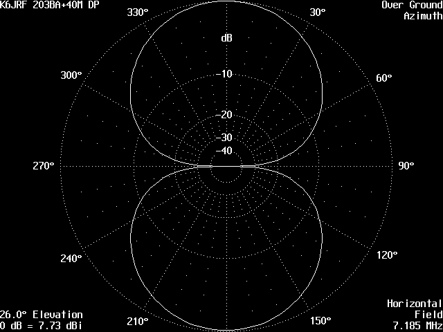 In this series, the 40M dipole is tested @ 7.185Mhz. The interaction, or lack of it, is shown in the plots. The azimuth
shows 7.73dB gain in the familiar symmetrical donut pattern. Note, if you look closely, there is a very slight (0.1db) loss
@ 180 degs.
|
|
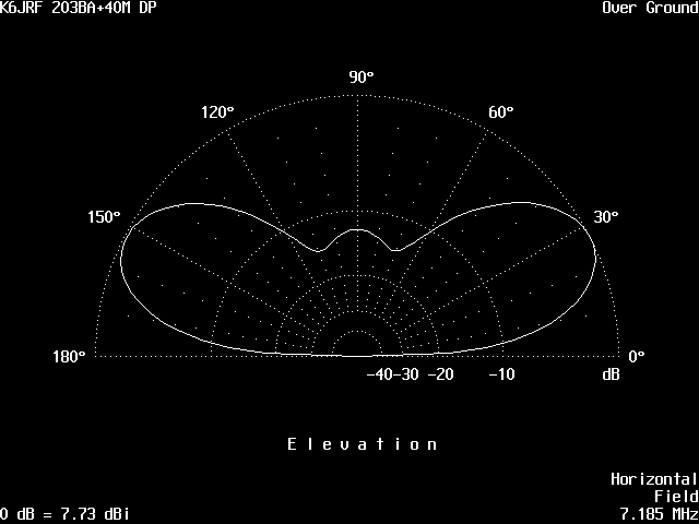 In this elevation plot, the take-off angle is 28 deg corresponding to 70 ft antenna height. The front and back gain is equal
. . . almost! It's easier to see that there is a slight loss (0.1db) off the backside.
|
|
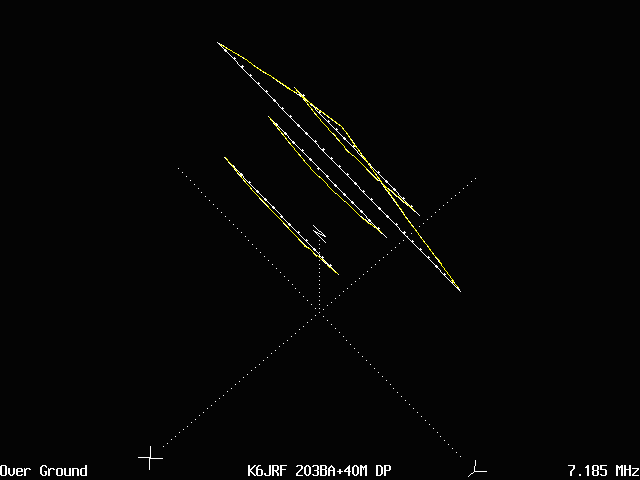 The current vectors (yellow) are shown for 40M operation. Note that all elements of the 20M yagi are acting as a secondary
reflectors for 40M operation. However, the main lobe is from the 40M DP itself.
|
|
|
Background 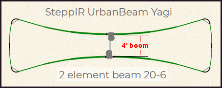 This design came from SteppIR's newest yagi antennas, called "UrbanBeam". It looks like a large "loop" antenna as
shown in the picture. And it's a two (2) element yagi from 20M to 6M on a . . four (4) ft boom! And it's a
40M dipole to boot.
 With a 4ft boom, the feed impedance is low - SteppIR design is 12.5 ohms. With such a low feed impedance, the operating SWR bandwidth is narrow before excesssive SWR becomes a problem. But since all SteppIR antennas can re-adjust the length of each element as the user moves frequency, the SWR is kept low. In addition, they use a 4:1 Un-Un (12.5 ohms to 50 ohms both unbalanced) to transform the low feed impedance to match the 50 ohm coax line impedance. For my design, I CAN'T adjust the element lengths as you transmit across the 20M band, so the operating BW will be limited. To increase the feed impedance, the spacing was increased from 4ft to 5ft. This raises the feed impedance to 15 - 16 ohms. So why not add more distance?? The funny thing is that the excellent F/B ratio degrades with increased spacing! I've modeled a lot of yagis but never thought of using such a short 4ft boom length. Also, typically, I've had poor results trying to add a lower frequency element, like 40mtrs to a 20 mtr yagi. As is well known, the higher frequency antenna normally suffers from this action. Even in first design (full size 40M dipole), adding the extra element (40M DP) upsets the beam's gain, F/B, etc so it's not my favorite thing to do. However, it reasons that you could add a LONG element as a REFLECTOR which shouldn't create a problem. So adding a Cushcraft D40 dipole, should work if it's added as a reflector. Also the D40 is partially resonant on 20M between the "loads". AO simulations confirmed that nicely. So it acts like a lossy reflector on 20M and is fully resonant on 40M. All of this good news requires a little extra boom, 10ft, to make a three (3) element 20M beam with the D40 serving as a 20M reflector and a 40M dipole. The only bad news is the COG is unbalanced. But that's not hard to solve. Short LJ203BA + D40 Dipole Using the LJ203BA [2els: Drvn + Dir + D40] as the starting point, an AO* run shows the following: * AO OPTIONS: 50 segments / halfwave ; 2D Pattern Resolution: 1 deg Impedance: 15.3 - j 28.4 ohms Total Losses 0.05dB Wire Losses 1.2% Load Loss 0.0 % Efficiency 98.8% At 11.0 deg Elevation: F/G 12.00 dBi F/B 29.52 dB B/W 68 degs Short LJ203BA + D40 DP - 20 Meter Performance 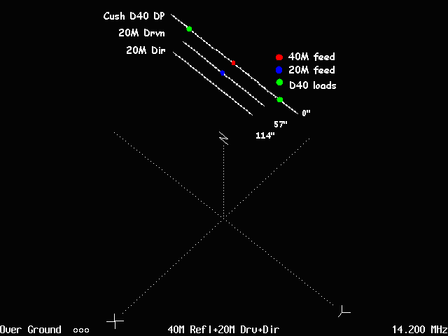 The projection plot shows the elements of the antenna and their placement on the boom. The 2 els comprising the 20M yagi
and the D40 element as the reflector. It is now possible to have an two (2) bands on one boom without significant sacrifice
of either band's performance. This IS great!
The projection plot shows the elements of the antenna and their placement on the boom. The 2 els comprising the 20M yagi
and the D40 element as the reflector. It is now possible to have an two (2) bands on one boom without significant sacrifice
of either band's performance. This IS great!The element separation is as shown: D40 Refl to 20M Drvn = 57" 20M Drvn to dir ele = 57" Total boom length = 120" AO analysis done in free space and over ground at 88ft. The short boom leads to a narrow operating bandwidth. However, for MY operating, it is perfect. Typical SWR shown by AO is below: 14.150 1.41:1 14.200 1.01:1 - Hairpin Match 14.250 1.49:1 |
|
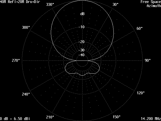 The performance in Free Space is clean for a short boom antenna. The impedance numbers are basically the same for
Free Space and Over Ground.
 Impedance Free Space: 15.3 - j 27.1 ohms Over Grnd: 15.3 - j 28.4 ohms Total Losses 0.05 dB Wire Loss 1.2% Load Loss 0.0% Efficiency 98.8% F/G 6.50 dBi F/B 23.98 dB Azimuth Beamwidth 68 deg |
|
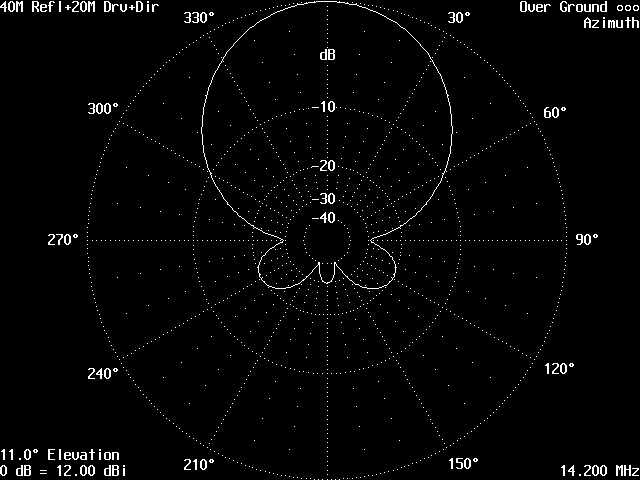 Over Ground @ 88 ft: The azimuth plot F/G = 12.00dBi with a clean 69 deg B/W pattern. F/B ratio is good - 29.5dB.
 |
|
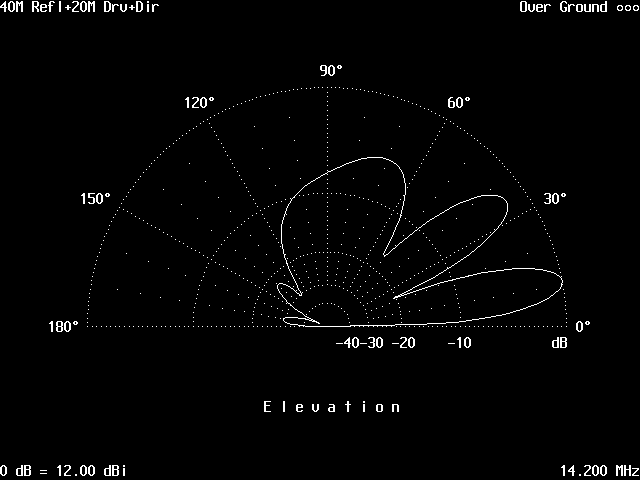 The elevation plot shows a clean forward projection pattern with 11 deg takeoff (DX) and 34 mid-angle pattern and a
70deg high-angle for USA work. Again the F/B ratio is exceptionally good - 29.5dB.
|
|
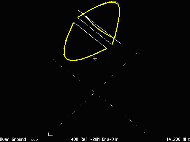 The current vectors (yellow) are shown for 20M operation. Here you see that 'proof' that the D40 acts as a "lossy" 20M
reflector as shown by the "weak" yellow current vector. This shows that the D40 is resonant on 20M. The F/B ratio is
mainly accomplished with the close spaced director with help from the D40 dipole.
|
|
Short LJ203BA + D40 DP - 40 Meter Performance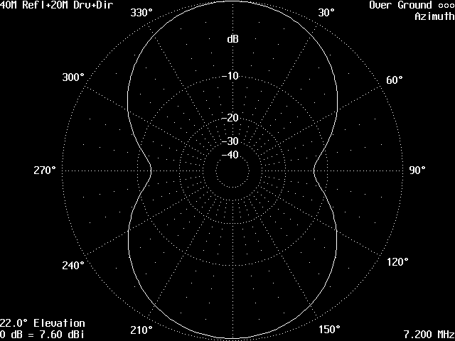 In this series, the D40 dipole was modeled @ 7.2Mhz. The interaction, or lack of it, is shown in the plots. The azimuth
shows 7.60dBi gain in the familiar symmetrical donut pattern. Note, if you look closely, there is a very slight (0.1db) loss
@ 180 degs.
In this series, the D40 dipole was modeled @ 7.2Mhz. The interaction, or lack of it, is shown in the plots. The azimuth
shows 7.60dBi gain in the familiar symmetrical donut pattern. Note, if you look closely, there is a very slight (0.1db) loss
@ 180 degs.The D40 specs show below are for Free Space and Over Ground @ 88 ft. Note that the Gain = 1.47dBi . . not 2.1 dBi . . b/c of the coil losses. ------------------ Cushcraft D40 Dipole Specs ----------------- ------ Over Ground: ---------------------------- Free Space: Imp: --- 40.2 + j 2.7 ohms ------------------- 47.6 - j 0.7 ohms Tot Loss:--- 0.54 dB ----------------------------- 0.45 dB Wire Loss:-- 0.4% -------------------------------- 0.3% Load Loss:-- 11.3% ------------------------------- 9.5% Efficiency:- 88.3% ------------------------------ 90.1% F/G: ---- 7.60 dBi ------------------------------ 1.47 dBi Az BW: --- 88 degs ----------------------------- 84 degs |
|
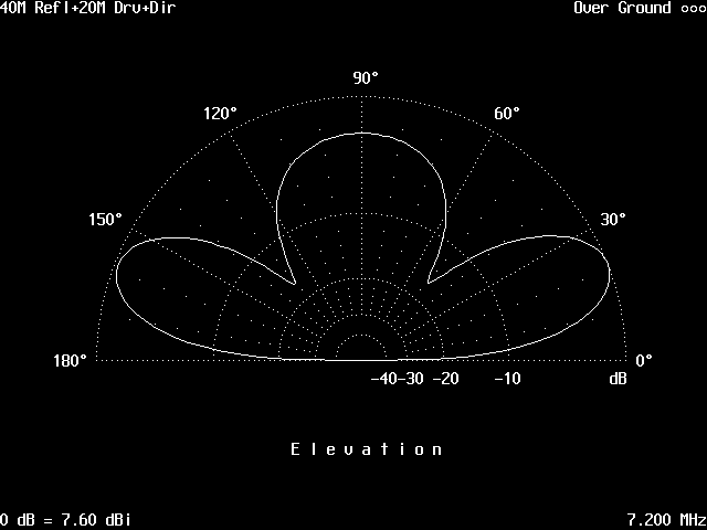 In this elevation plot, the take-off angle is 22 deg corresponding to 88 ft antenna height. The front and back gain is equal
. . . almost! It's easier to see that there is a slight loss (0.1db) off the backside.
In this elevation plot, the take-off angle is 22 deg corresponding to 88 ft antenna height. The front and back gain is equal
. . . almost! It's easier to see that there is a slight loss (0.1db) off the backside.AO analysis done over ground at 88ft of the full array shows the following results. The short spacing between the 20M driven and D40 dipole 'squeezes' the 40M operating bandwidth. Typical SWR from AO simulations for the 3el array and the D40 alone is below: Freq --- 3 el Array ---- D40 Alone ----- Remarks 7.150 ----- 1.90:1 --------- 1.82:1 7.200 ----- 1.01:1 --------- 1.01:1 ------ MFJ998 Tuner 7.250 ----- 1.93:1 --------- 1.81:1 The SWR is not significantly higher in the array b/c the D40 is not a broadband dipole due to the low Q, lossy coils. |
|
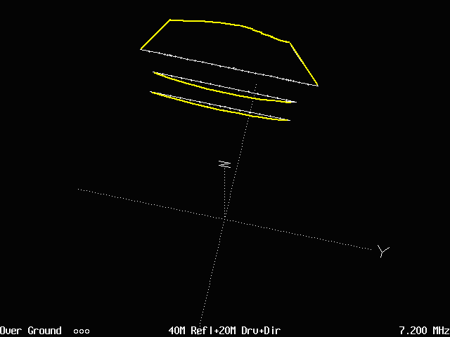 The current vectors (yellow) are shown for 40M operation. Note that all elements of the 20M yagi are acting as a secondary
reflectors for 40M operation. However, the main lobe is from the 40M DP itself.
|
|
|
Detailed Schematic 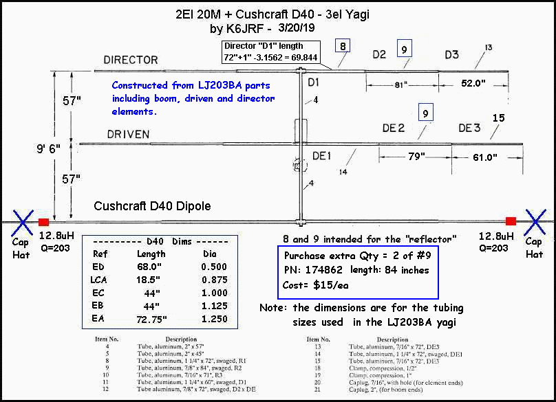
The insert box shows how the first section (D1) length and the second section (D2) are sections intended for use with the reflector. Since this antenna doesn't need one, those sections can be used. For the DRIVEN element, another #9 section is needed. You can purchase this part (PN:174862) from Hy-Gain/MFJ for $15 each. The URL is here. The "LJ203BA Parts List" is halfway down the page. Today, I have ordered two (2) pieces. The reason that both elements are longer than normal is due to the extremely close spacing employed in this antenna; less than 5 ft. This "loads" each element and requires added length to attain the performance and maintain negative reactance (apx -28 ohms) to use a Hairpin match system. I've also 'stretched' the boom in some simulations . . . added 1.5ft to each side and it didn't materially increase the feed impedance (still stayed around 15 ohms) but did materially DECREASE the F/B ratio to 10dB or so. I wouldn't have predicted that! The boom-to-mast plate/connector is moved between the driven and D40 dipole in order to balance the weight load. Not sure of the actual dimensions as of today. I will work out the details of what section numbers (#4 and/or #5) need to used and how much to cut off of each section. Now there won't be any extra torque on the tower. In order to clear the boom/mast clamp, the hairpin should be mounted facing toward the director. I've done this before in another design and there isn't any negative consequences of this mounting. |
|
Hairpin Taper Match Program 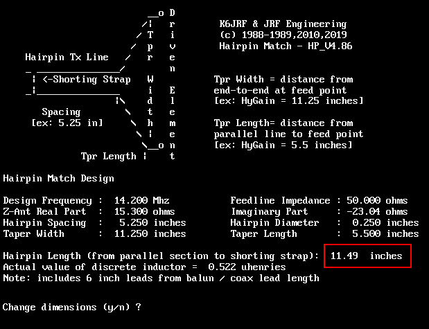 Some time ago, I wrote a hairpin matching program that considers the effect of the "tapering" (as shown in the sketch)
so that the inductive taper is not ignored. The program treats this taper and arrives at a more accurate placement
of the "shorting-strap".
 Recently, I added the effect of the balun's lead length to the driven element attachment point (shown in the previous chart) on the placement point for the shorting strap. The key parameters for the LJ203BAE + 40M Dipole design are shown in this chart. The matching frequency is the main parameter and the others are defaulted to my values; coaxial line impedance, HP parallel line width, starting taper LENGTH point and taper WIDTH need not be entered if you use my HP construction. The shorting strap should be placed apx 11.5" from the starting point of the parallel HP transmission line. This includes the effect of the balun output leads. This placement should be "close" and make a good starting point if not the 'perfect' matching point. The program is available [HP4_V4.86] . . click here to d/l it. This DOS program runs on all computer systems from Win98 thru Win 7 and 8.1. Simply follow the prompts and the output screen shows where to place the short. |
|
Tapered HairPin Matching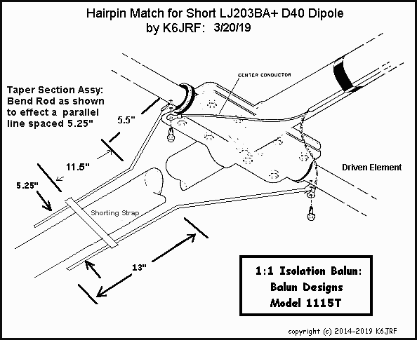 I recommend using this modified HP matching system since it is easier to match than the original "wide" Beta Match rod
system. This was used to match the 41' boom, 4el YO designed yagi with 9 ohm feed impedance. Was able to set it with
a few inches, so it's worth the time to construct.
 The length of the original rods are set to match a higher impedance (15.3 ohms) and are inconvenient to use. A better way is: Bend the rod at the 5.5" mark apx 40 degs, so the it forms a parallel transmission line w/ 5.25" spacing between the rods. You will need a shorting strap to "tune" the HP to match the driven element impedance (15.3 ohms) which is apx 11.5" from the beginning of the parallel part of the HP match. The sketch doesn't show a support mechanism but a 2" muffler clamp w/ a aluminum strap can support and space the HP. More pictures will be posted as I construct the yagi showing the details. I recommend using a balun such as the one shown here: here. Follow the construction as shown in the picture. |
|
|
AO Text File For those who have AO, this listing shows the format of a AO file. Copy and paste into a "text-file" editor such as Notepad and save it as "3EL-40M1.ANT" [that's my name for the file but it can be anything convenient]. You can download the file [3EL-40M1.ANT], click here Also can download the Cushcraft D40 file [CC-D40.ANT], click here 40M Refl+20M Drv+Dir Over Ground ;Free Space Symmetric 14.200 MHz 30 6061-T6 wires, inches H = 88' ; at 88 ft ;H2 = 74' ; at 74 ft 1 -57.0000 -247.250 H -57.0000 -179.250 H 0.5000 ; 68.0" 1 -57.0000 -179.250 H -57.0000 -175.750 H 0.6510 ; 3.5" 1 -57.0000 -175.750 H -57.0000 -171.250 H 0.8750 ;#3-HAT 1 -57.0000 -171.250 H -57.0000 -168.500 H 0.8750 ; 2.75" 1 -57.0000 -168.500 H -57.0000 -161.750 H 0.7500 ;#5-IND 1 -57.0000 -161.750 H -57.0000 -160.750 H 0.8750 ; 1" 1 -57.0000 -160.750 H -57.0000 -116.750 H 1.0000 ; 44" 1 -57.0000 -116.750 H -57.0000 -72.750 H 1.1250 ; 44" 1 -57.0000 -72.750 H -57.0000 00.000 H 1.2500 ; 72.75" 1 -57.0000 00.000 H -57.0000 72.750 H 1.2500 ;#10-feed 1 -57.0000 72.750 H -57.0000 116.750 H 1.1250 ; 44" 1 -57.0000 116.750 H -57.0000 160.750 H 1.0000 ; 44" 1 -57.0000 160.750 H -57.0000 161.750 H 0.8750 ; 1" 1 -57.0000 161.750 H -57.0000 168.500 H 0.7500 ;#14-IND 1 -57.0000 168.500 H -57.0000 171.250 H 0.8750 ; 2.75" 1 -57.0000 171.250 H -57.0000 175.750 H 0.8750 ;#16-HAT 1 -57.0000 175.750 H -57.0000 179.250 H 0.6510 ; 3.5" 1 -57.0000 179.250 H -57.0000 247.250 H 0.5000 ; 68.0" 1 0.0000 -212.0000 H 0.0000 -151.0000 H 0.4380 ; 61.0" 1 0.0000 -151.0000 H 0.0000 -72.0000 H 0.8750 ; 79" 1 0.0000 -72.0000 H 0.0000 72.0000 H 1.2500 ;#20 feed 1 0.0000 72.0000 H 0.0000 151.0000 H 0.8750 ; 79" 1 0.0000 151.0000 H 0.0000 212.0000 H 0.4380 ; 61.0" 1 57.0000 -206.0000 H 57.0000 -154.0000 H 0.4380 ; 52.0" 1 57.0000 -154.0000 H 57.0000 -73.0000 H 0.8750 ; 81" 1 57.0000 -73.0000 H 57.0000 -3.1562 H 1.2500 ; 69.844" 1 57.0000 -3.1562 H 57.0000 3.1562 H 2.2817 ; bracket 1 57.0000 3.1562 H 57.0000 73.0000 H 1.2500 ; 69.844" 1 57.0000 73.0000 H 57.0000 154.0000 H 0.8750 ; 81" 1 57.0000 154.0000 H 57.0000 206.0000 H 0.4380 ; 52.0" ;1 -199.0000 0.0000 H2 199.0000 0.0000 H2 0.8750 ;80M CD78 1 source Wire 21, center ;#21 center 20M :: #10 end1 40M 4 loads Wire 3, end2 3 uh 41 pf Wire 16, end1 3 uH 41 pf Wire 5, center 12.8 uH Q=203 Wire 14, center 12.8 uH Q=203 A three element Yagi using a 40M [Cushcraft D40] dipole as the 20M reflector provides decent gain on a short boom (9' 6") as well as two (2) band operation. Separate feeds are required for each band. D40 coil windings determine the "Q". For this configuration, Q = 203. These are ACTUAL dimensions; not from the assy manual!! Added another 20M dipole element that MUST be orthogonal to the main array otherwise it interacts with deleterious results to the main array! Check back here for more info . . . . my plan is to complete the construction of the LG203BAE with the Cushcraft D40 dipole. At present I have a Cushcraft D40 dipole and a partially assembled LJ203BA. The D40 specs are: 3KW power; 42ft tip-to-tip; 1.3sq ft wind load; 12 lbs weight. The present analysis represents is detailed for the D40 dipole. The loading coils and cap hats were measured and those measured value are incorporated into this design. Only some slight adjustments MAY be needed IMO. To this end, the following section was undertaken to test the theory. |
|
D40 Loading Coil
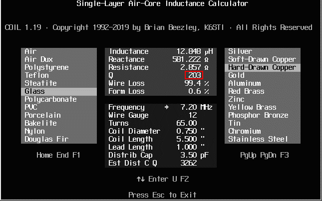 I measured it with my Fluke and Autex Research RF Analyst. Both measured EXACTLY 12.8xx uH . . . which was amazing! The K6STI
coil program makes three!
I measured it with my Fluke and Autex Research RF Analyst. Both measured EXACTLY 12.8xx uH . . . which was amazing! The K6STI
coil program makes three!The important info is the "Q". . . which is 203. The Q determines the antenna's efficiency; the higher the Q, the lower the losses. The D40's coil Q is low meaning the losses measured with the AO simulations are typical for the low Q. One way to improve the D40 is to wind new HIGH Q coils . . . with Q = 600 or more! The F/G gain would increase b/c the coil loss would decrease. For a coil Q=718, the F/G would increase to 1.78 dBi from 1.47 dBi which would improve the SWR/BW operation on 40M. However, there wouldn't be any increase in the 20M 3el array performance! |
|
|
Summary: The F/G, F/B are extremely good for a 10ft boom. It requires just a single 50 ohm coax feed line (for 20Mtrs). Now that I've figured out HOW to model the Cushcraft D40 dipole it appears that it will be a great reflector for 20M operation and give you another band to operate. Only need another separate 50 ohm feedline. After all is considered, the approach will make a 'balanced' load (D40 DP at the end) and requires two (2) feed lines for both 20M and 40M operation. The weight and wind-load considerations make it a good choice. |
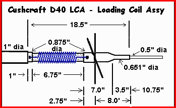 In general, antennas that have traps, loading coils, capacitors are more difficult to analyze. In AO, these are treated
as "loads". These electrical components change/alter the performance of the antenna and must be modeled properly. However,
constructing an "accurate" model is difficult.