|
K6JRF's Page formerly W6FZC WB Audio Techniques Page |
|
This Audio Page discusses the requirements to transmit good, clean SSB audio by
exploring fundamental radio and audio characteristics required to produce this kind of audio along with explanations
of how-to-do-this with the FT1000D. |
|
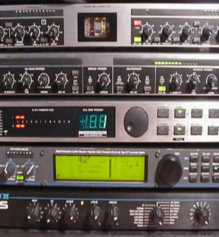
What makes good audio? This is a difficult question because audio can be evaluated using many different criteria. If I had to pick out just one characteristic, I'd pick 'BALANCE'! It makes no difference if the audio is wide band or narrow band, if it's balanced, it'll sound good! By this is meant, equal levels of signal from the lowest to the highest frequencies present in the output audio. Note that this does NOT have to be from DC to LIGHT! Your rig may only be capable of producing 300hz to 2.4Khz. That's ok. If the audio is 'balanced' across this spectrum, it can be very pleasing and 'articulate'. Certainly it will not sound as full and pleasing as a wideband 80hz to 3.2Khz audio signal would, assuming it's also balanced. Ah, that word 'articulate'. What does it mean? Webster's dictionary says 'made up of distinct syllables and words that convey meaning easily and clearly'. I guess that's what good audio does, doesn't it? You betcha! In wb audio terms, we try to get that quality over as wide as possible, from 50hz to 3Khz. And wider if your radio will allow. TS-950SDX can go from 50hz to 4.0Khz with a little educated push. My FT1000D, after mods, will go from 70hz to 3.2Khz. The FT1000MP and TS-870 are similar. We will discuss equipment and techniques necessary to achieve wb audio. How-to-do There are no hard and fast rules per se but there are certain steps that are necessary to produce this. The first starts with the microphone. As I've said before, keep your old Shure 444 in the bottom drawer. It will NOT produce clean, articulate wb audio. There are many choices for a quality mic which I mentioned in the AUDIO RACK and MIC section on the front page. Take the time to check these out to see if one might be right for you and your budget. This is very necessary step. Without a quality microphone, good Tx audio is not possible! The next choice concerns the audio dynamics. The term 'dynamics' means all steps normally associated with processing of the audio signal. These are: gating, compression, limiting, de-essing and equalization. In order to more comprehend these, click on the many links in the aforementioned section. Take the time to read the details contained on these sites. It will help you understand the 'terminology' and give you ideas as to what is needed in your equipment lineup. The chart below shows my current audio system equipment and the diagram shows all of the major interconnects between these equipments. These do change from time to time but the basic "ordering" concept has not changed. The numbers in blue refer to the input impedance of the stage except for the microphone where this is its output impedance. The balanced interconnections are employed between all units using either XLR or TRS connectors except for the Alesis Microverb. The output from the Alesis Microverb is unbalanced as is the FT1000D mic input connection so one channel of the Ebtech Hum Eliminator is used to ensure a ground loop free connection. The second channel is used for the Sony MD playback Eq, ensuring complete isolation between the audio processing system and the FT1000D. 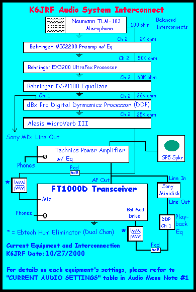 I firmly believe that the 'cleanest' sound is produced by;
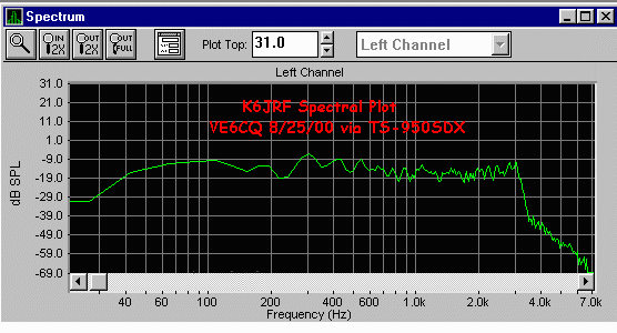
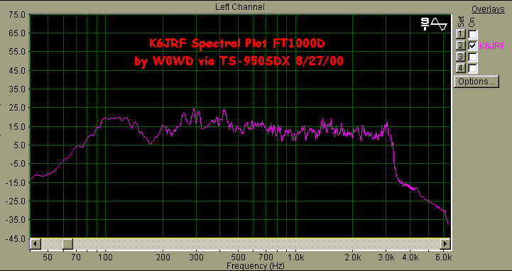
1) attenuating any 'unwanted' frequencies before they enter the main processing chain, 2) using equalization (DSP1100) and special effects (Ultrafex) processing ahead of any Gating, Compression and De-essing (or Limiting), 3) always adding reverberation (MicroVerb III) effects as the last piece of equipment. Therefore the my audio processing system reflects this philosophy. 1) For my voice, '400hz' is a no-no. Thus the Behringer MIC2200 preamp's eq stage is used to remove this frequency before it enters the processing. 2) The Behringer's EX3200 Ultrafex and DSP1100 are placed in front of the dBx DDP processor. This gives the DDP's compressor, limiter and de-esser the ability to compress, limit and de-ess the audio signal so that there is no chance of overdrive, harshness or clipping to the audio signal that drives the mic input of the FT1000D. 3) The Alesis MicroVerb III is at the end of the chain. The reason is simple; the gate in the DDP closes very quickly and thus the reverberation effect would be 'cutoff' unless the gate HOLD time is made much longer. This tends to defeat the action of the gate! Real ESSB Examples In order to see what's involved, what's better than a picture. These are spectrum plots made with SpectraPlus, a software program that turns your computer's sound card into a low frequency spectrum analyzer. The picture below shows the transmit audio response of my former radio, FT1000D taken by VE6CQ. The Tx bw is basically flat from 50hz to 3.1Khz. The key is the balance that it possess. The difference from top to bottom is less than 3dB - 4dB. Also the mid range frequencies are slightly attenuated so as to bring out the resonant bottom and top frequencies, where the 'articulation' lies. The next two pictures show the most recent plot of yours truly taken by VE6CQ and W0WD. Note that with the new preamp (described below), I've reduced the heavy mid range frequencies and ended up with a more balanced audio from 'bottom' to 'top'. With the slight rise around 3Khz, brightness and clarity are present in the transmitted audio making it 'articulate'
FT1000D Techniques The following sections are specific to the FT1000D radio and show my current alignments and adjustments along with the external audio equipment and its settings. I've tried to maximize the TRANSMIT upper frequency point and did this by adjusting all oscillators and trimmers that control this in the radio. The 8.67Mhz IF (TC4001), 55.48Mhz (L4071) TCP and the two (2) capacitive trimmers (TC4006 for USB and TC4007 for LSB) were adjusted to get the highest possible frequency response from my InRad filters in the '2.4K' position (InRad #716 and #707C). The results are shown above by the frequency response spectrum plots.
Results of TCP Adjustments The following chart shows the results of the TCP adjustments on the final Tx audio when equalization is employed as detailed below. The charts show my current alignments and adjustments to my FT1000D along with the external audio equipment and its settings.
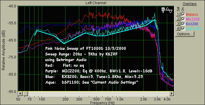
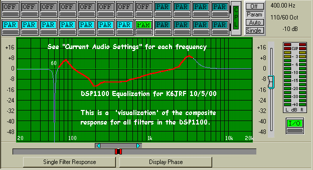
The low frequency response 'peaks' around 400hz and if not attenuated, makes the resultant Tx audio very restricted sounding like Broderick Crawford of the now famous "Highway Patrol" series! Note that BOTH the low and high frequency response is at least 10dB down from the response at 400hz. Now we add in the Eq stage in the MIC2200 preamp. The PURPLE trace shows the pink noise response with 400hz attenuated by -10dB. Removing this frequency (and adjacent frequencies) allows the higher frequencies to be heard. Next the Behringer EX3200 Ultrafex response is shown in the BLUE curve. Now the low frequencies (50 to 100hz) have been eq'ed to the same level as the high frequencies. The low and high frequency losses are typical all of ALL radios and would be very representative of what it takes to get flat transmit audio in most any radio! Note that it takes at least 10dB of additional high end gain to get flat high frequency (1K - 3Khz) response out of the radio. The AQUA chart shows the response after the Behringer DSP1100 in included. Now the final 'polish' is added to the Tx audio. The 200hz area is attenuated by -8dB but the 80-100hz area is left flat. The gives 'balls' to the audio without the boominess that the 150 - 200hz frequency area gives. Next a rising response from 1Khz to 3.2Khz is added to give the Tx audio the 'clarity' that is so important to balance the heavy bottom response. The chart below is a 'visualization' of all equalization currently used. Note that the highlighted section of the AQUA chart line compares almost identically with the RED enhanced portion of the BLUE line. The 60 hz notch is used to kill the 60hz compressor noise from my room air conditioner. The exact frequencies can be found in the Behringer DSP1100 section of the "Current Audio Settings" table below. This software can be download from the Behringer web page by clicking on the Editor Software link. It's designed specifically for the DSP1100 but can be used to visualize any eq combination as long as the frequency, bandwidth and level are known.
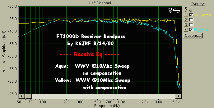
The following chart shows the FT1000D RECEIVER characteristics using the present filters (InRad #710 and #707C) in the '2.0K' position. The #710 is a 6Khz bw filter as is the CMF, #707C. The cascaded bw is around 5Khz. The AQUA chart shows the raw response of the FT1000D as it is currently adjusted. This is typical of most receivers with the exception of the TS-870! The Yellow chart shows the compensation applied to SpectraPlus to allow accurate comparisons to other stations without introducing errors from your receiver.
Sweep Test Setup
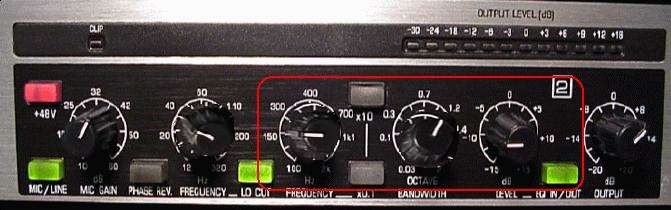
Audio Dynamics Settings: Here are the current settings for all of my audio equipment. Today (8/25/00), I changed most ALL settings! Why? Because I've replaced the Aphex 107 Preamp with the Behringer UltraGain 2200. This new unit has a parametric stage (boxed in red) that allows attenuation of the heavier low mid frequency range (200 to 400hz) BEFORE it gets into the following stages. Also this frees up the DDP to do some other processing.
After installation of the Collins filters (see main menu, #7), the audio took on a heavier flavor due to the excessive mid frequencies. Couple this with the increased low and high frequency response, made the transmit audio sound mushy and heavy in the 'mids' with some 'tearing' on the top side.
[Current Audio Settings: Updated Jun 11, 2002]
The Aphex 250 AE was replaced with the Behringer EX3200 Ultrafex. This device is similar to the 250 but it is much more straightforward to setup and use. These devices are necessary to give clarity and brightness to the Tx audio since the radio's filters tend to attenuate higher frequencies and 'muddy' the audio clarity.
The DDP's TCM setting was changed from 500us to 1.5ms. This allows more time to set up the VCA gain and allows the processor to 'handle' the high level of energy at 3Khz that I'm using. Without this higher TCM setting, the transients were causing distortion and tearing. This tip thanks to N8QW. Equipment Alternates: Many say that the 'stack' of audio equipment is too much both in cost and physical size. Isn't there something smaller and more compact that does the job? The answer is Yes! W2IHY markets an all-in-one audio processor called the 8 Band Equalizer. It's small and compact, has provision for different mic inputs including XLR connectors, can provide 5V phantom power and has a unique adjustable noise gate that cuts out background noise. It can purchased complete or in kit form including a cable to plug directly into your radio. This make a good alternate to going the 'full' audio route and may appeal to the majority of hams. |

|
Send me |