|
K6JRF's Page formerly W6FZC FT2000 VOX Circuit Mod Page |
|
This Vox Mod Page details ckt value changes to the FT2000 Vox Ckt contained on the
"Main Board Unit" to make it more responsive to the 'male' voice and less susceptible to false triggering and lock up.
The note includes the effects of both the VOX and Anti-VOX ckts in detail. This is an updated version as I found that some components in the "Vox" portion of the ckt were omitted and for other components had missing Spice models. These have been found and this update is more accurate than previous versions. I also switched from MSim's "PSpice" to a newer, more compact analysis program called "5Spice" written by Andresen Software. It features almost intuitive operation, has many powerful features and and allows the import of various Spice models so that the ckt can be simulated using the actual real world parts. Click here to see more information on this fine circuit analysis product. |
|
Problem: I really enjoy VOX operation on my radio but it's usually so 'bad' that I'm forced to not use it! One of the main reasons is that it always false triggers when you drop a pencil on the desk or open a coke can or make any sort of noise, including high frequency noise from the speaker! I'm sure you have seen the same problems. But it also doesn't fire for the "typical" male voice, or if it does, as your volume drops, so does the Vox in the middle of a word. Very frustrating! We've all been there. The FT2000 is no better than most all other radios. I see that Yaesu didn't "learn" from my mods that were made to my FT1000 here. They should have! So I've modified the Vox ckt using the techniques developed for the FT1000. The complete analysis and recommendations are detailed in the sections below. 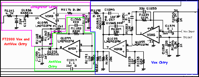 The "AntiVox" portion also needs to be modified b/c the low frequency gain (10hz to 100hz) needs some parts changes to increase the gain so that it can "hold off" the Vox portion from false triggering. 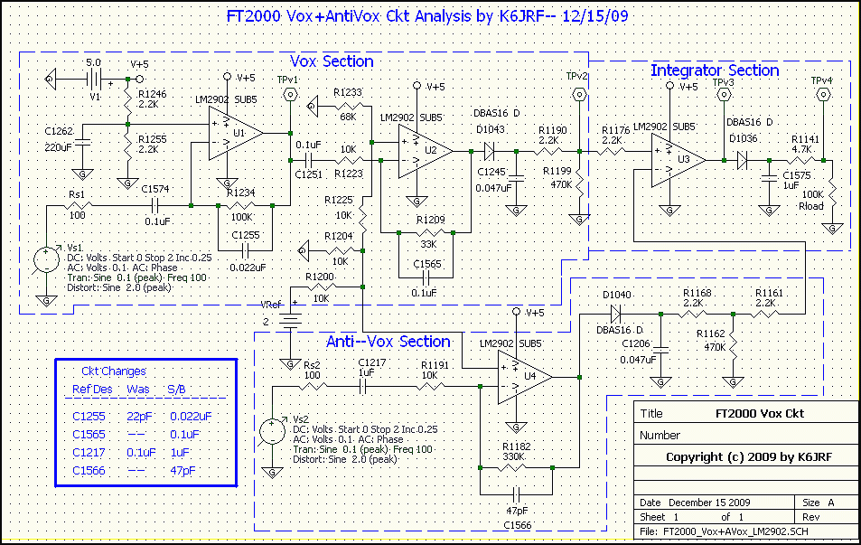 Normal Ckt Operation: To understand how this ckt performs, the following examples show it with a normal input and the second, with a high antivox signal. In the first case, the ckt performs and responds to a "vox" input signal from the mic. In the second, the ckt is prevented from operating b/c the antivox level "locks-up" the output and so the vox doesn't work. 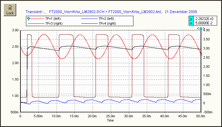 The chart above shows the normal VOX operation where the input signal (red) is 100hz and the A-Vox signal is 200hz but very
low in amplitude. The input vox IC (U1) amplifies the signal (100hz @ TPV1). The antivox signal is amplified in U4 (shown in
blue @ TPV2) and is the "holdoff" signal. The processing is done in the "Integrator" section by U3. The output is shown in by the
"square-wave" signal (in dark RED @ TPV3) prior to half-wave rectification (D1036) and integration by C1575 (1uF). This is shown by
the black trace @ TPV4. This signal keys the Tx portion of the radio as long as the signal stays active.
 |
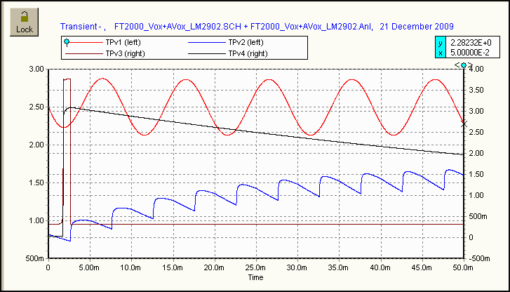 When the antivox signal (200hz) increases in amplitude, as shown by the above chart, the vox portion of the ckt is "locked" and doesn't output. This is shown by the long black trace (TPV4) that fired briefly at the beginning but is now prevented from triggering due to the 'strong' antivox signal (shown in blue @ TPV2). Thus as loud as you try, the vox will not fire the radio. |
|
VOX Analysis: The following analysis can best be understood by parceling the schematic to the separate sections. The "VOX" section is shown below. This schematic represents the Vox portion captured into 5Spice and checked, ready for a ckt simulation. 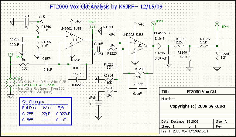 5Spice Simulation - VOX Ckt: Once the radio's VOX ckts were captured into 5Spice, a ckt simulation was run to map the ckt's frequency response. The main outputs are shown in the chart. As you can see, the response is similar (if not identical!) to the FT1000 Vox ckt response. The Reference Designator (Ref Des) have been preserved in the schematic so you can see where the ckt parts are on the Main Board Unit. Use the Service Manual (#1) that is posted in the "Technical Supplement Menu" section for your guidance. It's flat from 200hz to over 5Khz. It's the extended upper frequency response that causes the pencil-drop or a paper-shuffle to trigger the ckt. The values for the "stock" ckt are shown in the schematic as the "WAS" values. 5Spice VOX Ckt Value Changes: 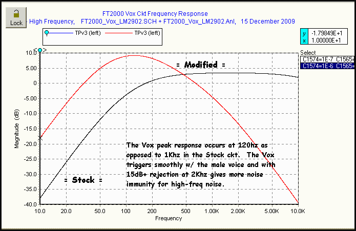 Using the values gained from the S5pice simulation results in the chart to the right. You see that the response has been
shifted considerably down toward the male voice with the center frequency at 121hz. In addition, the "GAIN" of the ckt has been
reduced (about -4db), so that you now have more control of the "VOX" gain setting using the front panel knob.
Using the values gained from the S5pice simulation results in the chart to the right. You see that the response has been
shifted considerably down toward the male voice with the center frequency at 121hz. In addition, the "GAIN" of the ckt has been
reduced (about -4db), so that you now have more control of the "VOX" gain setting using the front panel knob.The new values are in the "S/B" column. For those who might complain that it's TOO low, you can see that the response curve is very board and will respond to the male or female voice nicely. |
|
ANTIVOX Ckt Analysis: The following analysis can best be understood by parceling the schematic to the separate sections. The "ANTIVOX" section is shown below. This schematic represents the Vox portion captured into 5Spice and checked, ready for a ckt simulation. 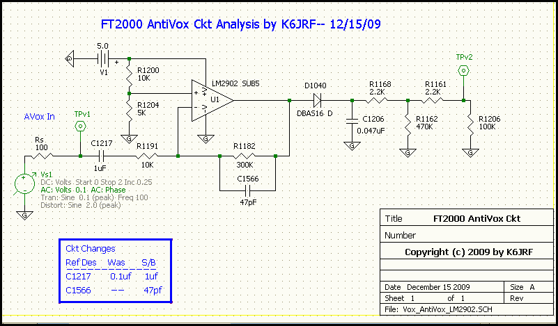 5Spice Simulation - ANTIVOX Ckt: Once the radio's ANTIVOX ckts were captured into 5Spice, a ckt simulation was run to map the ckt's frequency response. The main outputs are shown in the chart. As you can see, the response is similar (if not identical!) to the FT1000 AntiVox ckt response. The Reference Designators (Ref Des) have been preserved in the schematic so you can see where the ckt parts are on the Main Board Unit. Use the Service Manual (#1) that is posted in the "Technical Supplement Menu" section for your guidance. It's flat from 200hz to over 5Khz so it's upper frequency response is fine. The area that's 'short' from 10hz to 100hz. This is were you need 'extra' antivox to ensure that there's minimal false triggering of the Vox ckt. To ensure this, the largest amount of antivox drive should be generated. The values for the "stock" ckt are shown in the schematic as the "WAS" values. |
5Spice ANTIVOX Ckt Value Changes: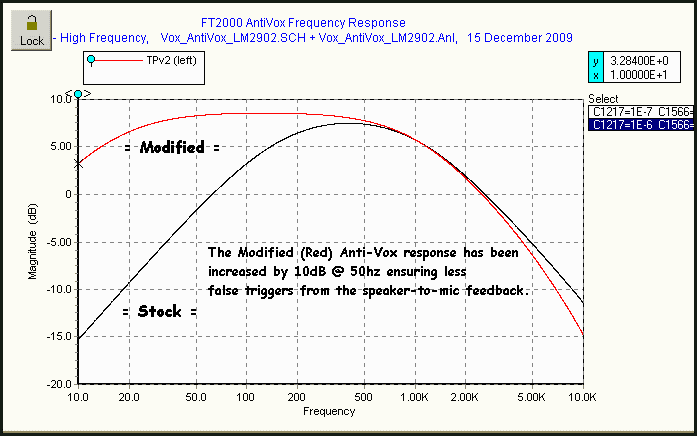 Using the values gained from the 5Spice simulation results in the chart to the right. You see that the response has been
shifted down toward 10hz to ensure extra antivox drive is available at low frequencies. In addition, the "GAIN" of the ckt has
not been reduced there is nothing to be concerned about.
 The new values are in the "S/B" column. |
|
Instructions: The main task now is to replace the indicated chip-capacitors (c-caps) with the preferred values generated in the 5Spice simulation analysis. To that end, the picture shows the desired area on the Main Board in section "B-5". 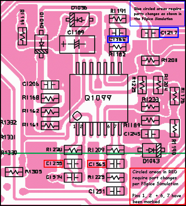
There are three (3) c-caps that need to be replaced for the VOX ckt; two (2) c-caps for the ANTIVOX ckt. At one time, I considered "adding" an additional c-cap to the existing c-cap but this wasn't really practical. It's just as easy to replace the value with the new value. The pins of the main IC, Q1099 have been marked as an aid. An added c-cap is required for "C1565" as well as "C1566" since the pads are blank. The c-caps are outlined in red and the Vox ckt value changes are: C1255: 22pf -> 0.022uf C1565: blank -> 0.1uf The c-caps are outlined in blue and the AntiVox ckt value changes are: C1217: 0.1uf -> 1uf C1566: blank -> 47pf The opamp IC, Q1099's pins also have been highlighted (1,2 + 6,7) as possible junction points for added c-caps. Refer to the schematic to see the significance of the marked pins. |
|
Main Board Access: All of the c-caps and c-resistors are mounted on the top side of the PCB so you can access them without having to remove the Main Unit Board. The following parts are available from Yaesu/Vertex Parts Department at 714-827-7600 x-6800. Detailed Chip Cap Info: Ref Des ------- Value ---------- Part Number -------------- Yaesu PN --------- Price/Ea C1255 -------- 0.022uF -------- GRM40B223M50PT --------- K22170821-------- $0.16 C1565 -------- 0.1uf ---------- GRM188B11C104KA01D ----- K22124805 ------- $0.12 C1217 -------- 1uf ------------ GRM188B10J105KA01D ----- K22084801-------- $0.03 C1566 -------- 47pf ----------- GRM1882C1H470JA01D ----- K22174227-------- $0.08 The following is a brief explanation of the required steps. If you have the prerequiste skills and the tools to complete this project, then no further explanation is required. Your de-soldering skills should be just as proficient as your soldering skills since you will have to remove some of the c-caps and then re-solder with the new values. If you're not proficient, then get somebody who can do this for you. The VOX-ANTI VOX circuitry can be found in the Main Unit schematic in area B5. 1) Remove the TOP and BOTTOM covers of the FT2000. 2) Turn the radio over so that the back side (I/O connectors) are facing you. 3) Then remove the bottom "shield" cover to gain acess to the Main Unit Board. 4) Next, disconnect the cable harness that passes directly over Q1099 so you have access to the c-caps around Q1099. 5) Using the schematic guide, remove the existing c-cap (C1255) and replace with the indicated values. 6) For C1217, remove the present c-cap and replace with the correct c-cap. 7) For C1565 and C1566, just add the indicated c-cap since the solder pads are open. 8) Reinstall the connectors from the removed harness. 9) When complete, reinstall the shield cover first, then the BOTTOM and TOP covers in that order. COMMENTS: The VOX operation with this change is materially better, and that's an understatement! The vox picks up instantly and doesn't drop out with normal voice level variation. It doesn't false as the other ckt configuration did. In fact, you can give the "ssss" sound (clenched teeth blowing "sss" sounds which is around 2Khz) within 6" of the mic and the VOX won't fire but a normally spoken "word" will! You now have better control of the VOX gain setting via the front panel knob; I find that a VOX Gain setting of 10:30 to 11 o'clock will pickup your voice within 3" to 4" of the mic. The best "delay" time is around 380msecs. A good "Anti-Vox" (Menu #042) setting lies in a range between 25 and 50. This change makes VOX operation a pleasure. . . very smooth, seamless VOX pickup that responds uniformly throughout the microphone's field of pickup. No other mods need be done prior to this modification. |
|
Send me |