|
K6JRF's Page formerly W6FZC ESSB Audio Techniques Page |
|
This FT2000 Page discusses the techniques to attain clean ESSB (Extended SSB) audio
in a 3Khz SSB BW by exloring fundamental radio and audio characteristics required to produce this audio along with
how-to-do-this using both the radio's internal EQ plus external audio equipment. |
|
A few days ago, I heard K9DN, Don on 20mtrs. He has been experimenting with his FT2000's
SSB Tx audio and DEQ2496. Hearing that, I broke in and gave him the link to this web page and suggested that he give the settings a try to get him into the "ballpark". The next day, I heard him again and his SSB Tx audio was really nice, a clean, balanced sound. I congratulated him and he said that he used the settings at the bottom of this page to get him into the right range. Then he added some upper frequency polish. This is the first that I've found where the settings were able to be "ported" to another radio. I guess that shouldn't be too surprising since he has the same (radio, mike, and EQ) as mine. In any regard, you have made my day! Tnx, Don. |
|
What makes good audio? This is a difficult question because audio can be evaluated using many different criteria. If I had to pick out just one characteristic, I'd pick 'BALANCE'! It makes no difference if the audio is wide band or narrow band, if it's balanced, it'll sound good! By this is meant, equal levels of signal from the lowest to the highest frequencies present in the output audio. Note that this does NOT have to be from DC to LIGHT! Your rig may only be capable of producing 200hz to 2.4Khz. That's ok. If the audio is 'balanced' across this spectrum, it can be very pleasing and articulate and not cause splatter. Certainly it will not sound as full and pleasing as a wideband 60hz to 3.2Khz audio signal would, again assuming it's also balanced. Ah, that word articulate. What does it mean? Webster's dictionary says 'made up of distinct syllables and words that convey meaning easily and clearly'. I guess that's what good audio does, doesn't it? You betcha! In WB audio terms, you should try to get a quality signal over as wide a WB as possible. The limits of 50hz to 3Khz do satisfy that requirement. If your radio will produce a wider bandwidth, then all the better. The Kenwood TS-950SDX Tx bw is 40hz to 4.0Khz with a little educated push. The FT2000's bw is 50hz to 3Khz as it comes from the box. Microphone There are no hard and fast rules about what mics to use but investing in a "professional" mic is a big step in the right direction. It is one of the key elements in the ESSB "chain". Keep your old Shure 444 in the bottom drawer. It will NOT produce clean, articulate WB audio. There's a number of 'good' mics on the market today that won't break the bank. The Marshall line of mics has been expanded into a number of models. Most feature a large diameter (1") condenser element and they are very reasonably priced. They have also added a tube line of mics which have been given good reviews. Their V69 tube mic has been highly rated in reviews but it's a bit pricey. A more reasonably priced tube mic is the V960. There are many choices for a quality mic which I mentioned in the AUDIO RACK and MIC section on the front page. Personally I think the Neumann mics feature smoothness, lack of 'peaks' and are excellent choice albeit expensive. Take the time to check these out to see if one might be right for you and your budget. This is very necessary step. Without a quality microphone, good Tx audio is not possible. The Heil HC4 cartridge should stay in the drawer! External Audio Equipment The next choice concerns the audio dynamics. The term 'dynamics' means all steps normally associated with processing of the audio signal. These are: gating, compression, limiting, de-essing and equalization. In order to more comprehend these, click on the many links in the aforementioned section. Take the time to read the details contained on these sites. It will help you understand the 'terminology' and give you ideas as to what is needed in your equipment lineup. The chart to the right shows my current audio system equipment and the "block" diagram shows all of the major interconnects between\ these equipments. The connections are standard and you will find that the interconnections shown will be required. Of course, these do change from time to time but the basic "ordering" concept has not changed. The numbers in blue at the top right side of each equipment, refer to the input impedance of the stage except for the microphone where this is its output impedance. The balanced interconnections are employed between all units using either XLR or TRS connectors except for the Alesis Microverb. If you aren't careful, you will get "hum" and that's indicates that you have a "ground-loop". The use of balanced interconnections (XLR) will ensure that these are minimized.  The output from the Alesis Microverb is unbalanced as is the FT2000 mic input connection so one channel of the
Ebtech Hum Eliminator is used to ensure a ground loop free connection.
The second channel is used for the Sony MD playback EQ, ensuring complete isolation between the audio processing system and
the FT2000.
The output from the Alesis Microverb is unbalanced as is the FT2000 mic input connection so one channel of the
Ebtech Hum Eliminator is used to ensure a ground loop free connection.
The second channel is used for the Sony MD playback EQ, ensuring complete isolation between the audio processing system and
the FT2000.Audio Equipment Hierarchy I firmly believe that the 'cleanest' sound is produced by; 1) attenuating any 'unwanted' frequencies before they enter the main processing chain, 2) using equalization (DEQ2496) processing ahead of any Gating, Compression and De-essing (or Limiting), 3) always adding reverberation (MicroVerb III) effects as the last piece of equipment (if you use reverb). Therefore the my audio processing system reflects this philosophy. 1) For my voice, the band of frequencies between 300hz to 400hz is a no-no, so the Behringer MIC2200 preamp's EQ stage is used to remove this band of frequencies before it enters the processing. 2) The Behringer's Ultra Curve DEQ2496 is placed in front of the dBx DDP, Digital Dynamics Processor. This gives the DDP's compressor, limiter and de-esser the ability to compress, limit and de-ess the audio signal so that there is no chance of overdrive, harshness or clipping to the audio signal that drives the mic input of the FT2000. 3) The Alesis MicroVerb III which was at the end of the chain has been removed. The reverb effects are not normally heard unless signals are S9 + 30db or more so this function is mostly useless. However, if you use one, it should be at the end of the chain since if a Gate is use, it will close very quickly so the reverberation effect is 'cutoff'. If you make the Gate unaturally long, you are defeating the reason for the gate! Real ESSB Example  In order to see what's involved, what's better than a picture. These are spectrum plots made with SpectraPlus, a software program that turns your computer's sound card into a low frequency spectrum analyzer. The picture below shows the transmit audio response of my former radio, FT1000D taken by VE6CQ. The Tx bw is basically flat from 50hz to 3.1Khz. The key is the balance that it possess. The difference from top to bottom is less than 3dB - 4dB. Also the mid range frequencies are slightly attenuated so as to bring out the resonant bottom and top frequencies, where the 'articulation' lies.
FT2000 Internal Menus Settings The following sections are specific to the FT2000 radio and show my current alignments and adjustments along with the external audio equipment and its settings. Unlike my former FT-1000D that required "manual" adjustments inside the radio, most of the FT2000 adjustments can be made via the menus accessible from the front panel! This truly makes it very much easier to adjust the radio's parameters.
* the "low" [EQ1], "mid" [EQ2] and "high" [EQ3] EQ ranges should be set at shown. If so, you can be assured that the
Tx BW is flat from 50hz to 4Khz as shown in the white noise Tx sweep chart below. Tx and Rx Sweep Tests The SP chart shows the measured response of the FT2000 (w/ EDSP 11.54 and Main 1.51) for both EQ and non-EQ.  For the 50hz - 3Khz setting [Menu #85 - "1 - 30"] you may need external EQ since the overall curve needs to be shaped to attenuate the muddy low-mid frequencies. As you can see, it's gently slopes downward (about 6dB) from 50hz to 3Khz! A commercial AM station would have apx 5.5Khz bw. Personally, this form of EQ is "tiring" to the ears b/c it lacks 'presence' mainly b/c "all" frequencies are equally weighted. Most male voices have a heavy low-mid (200 - 400) frequency presence and that 'kills' the audio IMO. The chart shows an Over-The-Air (OTA) capture of the "Broadcast" equalization as recorded by W5GI using a SDR Flex5000. The plot exhibits a gentle taper reflecting a typical AM broadcast EQ used on "talk-radio" programs.
The rcvr's low frequency response is impressive. Tests w/ the FT-1000D, showed absolutely no response below 100Hz, so the 20Hz response (flat to 30hz) of the FT2000 is satisfying. The main settings for these Rx BW measurements were; IPO = ON, RFlt = 15Khz; VRF = OFF; Width = Max. Any of these settings will effect the response curve, so they need to be set as shown to guarantee the measurement is the maximized. FT2000 "DEQ2496" Tx EQ The previous "Radio+Rack" and "MinRack" EQs have been removed since those used audio gear which is no longer present. As you've read, I like to experiment to find the "ultimate" EQ so I tried different ways of attaining nervana but haven't done so todate. But, in the meantime, I'll have fun and discover new 'tricks'. The current EQ is one of those new ways using the DEQ2496 (Short for "2496").  The interesting part is the way that it was "born". The 2496 has some interesting properties, one of which is the built-in
pink noise generator (PN). It can be connected internally to the EQ stages (GEQ, PEQ, DEQ, etc) by access to the
"I/O" #1 menu. As the picture shows, after you set the output level (-20db), press the large wheel to start the PN
generator.
The interesting part is the way that it was "born". The 2496 has some interesting properties, one of which is the built-in
pink noise generator (PN). It can be connected internally to the EQ stages (GEQ, PEQ, DEQ, etc) by access to the
"I/O" #1 menu. As the picture shows, after you set the output level (-20db), press the large wheel to start the PN
generator. Using SP, a "calibration" run was made to give a "baseline" from which to compare. That's shown in the "yellow" trace. To generate that chart, all modules are bypassed using the "BYPASS" menu. After the chart completes, the 2496 modules are re-inserted inline and another PN sweep is made of all 2496's modules. That portion is shown via the "red" line. It uses the PEQ, DEQ, DYN and LIM modules with the GEQ being bypassed. The "red" chart shows a number of small "dips" which represent the EQ; for example, a -4db dip at 200hz plus a +4db peak at 2.3Khz. The "blue" trace shows the complete EQ using all three (3) audio processors in my rack. There are two (2) program inserted filters, 1111hz and 1824hz that were detected when a FBD (FeedBack Destroyer) sweep was done. These are automatically added to the FBD and PEQ. In this case, it represents room and fan noise that the unit detected and minimized. A nice feature, indeed! 
Checking the "blue" line in the chart shows a "hole" starting at apx 140hz that extends to 200hz and then slowly rises to be flat around 400hz effectively attenuating the muddy low-mids. Note that this EQ doesn't have as much of the low-mids removed as previous EQs. The EQ is flat from 500hz to almost 3Khz so that's one reason way the low-bass is not obvious. Overall this EQ has a lot of 'fullness' but does not sound like it is! 
The SP chart captured by me from a W0WD MD recording shows that it follows the above EQ chart very well. The mid-section is basically flat from 300hz to 3Khz except for the two room and fan noise filters. 
The EQ was born by capturing my voice via the TLM-103 w/ no EQ onto a Mini Disk. The recording was then captured by SP and a "raw" chart emerged. From this the "bad" spots were attenuated where needed including the low-mids and even the low-bass frequencies. Only areas that needed EQ were 'touched' to remove "peaks". The high frequency area needed some added gain.
The MP3 clip below demonstrates the sound of this EQ "Full_Rack_EQ". It was recored by NA1A and sent as an MP3 file. There's some adjacent frequency "noise" on the recording but the merits of the EQ can be heard. One of the reasons for the "birth" of this EQ is due to using my station's playback capability. It requires that the radio's EQ be turned off to guarantee a flat playback response. If you "forget", then the playback will not sound natural. Because of "forgetting" and having to flip too many switches, I designed this EQ. All things considered, this EQ produces full but natural sounding SSB audio on the FT2000 and is usable for; - Rag-Chew: Use "1-30" [50hz to 3Khz] BW setting in menu #85; turn radio EQ off, PROC "Mic EQ" is not displayed plus PROC = "OFF". Use the settings contained in the "Current Audio Settings" at the bottom of the page. - DX: Please read the inset below on the use of the processor.
FT2000 Tx No-Eq Sweep Tests Using the radio settings in the table (the Parametric EQ [PE1, PE2 and PE3] were NOT used) a white noise sweep was preformed on all of the various FT2000 selectable bw. The results are shown the "Non-EQ-sweep" tests. Interestingly, the 100hz to 2.9Khz input rolloff is more like 150-160hz instead of 100hz. Also as you see, the Non-EQ response shows a lot of passband droop, about 15dB! The "wall" at 3.0Khz is due to the DSP and you can't get around it! The "3000wb" sweep was omitted b/c the 1-30 produces a flatter sweep with less droop! All charts were made using SpectraPlus Pro. Cal Path: The green plot called "Cal Path" shows the flatness of the measuring system. It's serves as the path calibration for the proceeding measurements showing the overall flatness of the laptop and SP-P. Therefore the sweep signal sent into the FT2000 is 'flat. The output response, whatever it is, is due to the radio's internal compensation. Below 40hz, theres a 'rolloff' due to the laptop. However the radio doesn't respond to those low frequencies so there's no need to EQ that frequency band.   FT2000 Playback EQ Sweep Tests - "Flat Response" Most ESSB enthusiaists have the capability to capture Tx audio, display its BW using SpectraPlus (or similiar) and finally, play it back to you as a faithful reproduction of what was captured. This latter function requires that your radio's playback capability be compensated to be 'flat'. Not all radios have the same playback BW; the FT2000 captures the signal from 40hz to 4Khz, however, it can only playback from 45hz to 3Khz. That's where the brick wall formed by the DSP third stage "IF" sets in . However, even with that minor limitation, the EQ must be adjusted to be flat. To that end, the chart shows the FT2000 playback response after using the dbx DDP's channel1 for the (see block diagram) EQ. 
The DDP has three (3) stages of parametric EQ and the values are shown that flatten the FT2000 playback response. Note that the latest FW (11.54 + 1.51) are loaded into the radio. Now that I have a "real" antenna up on the tower, it can be used to tune a WB signal to check the Rx SSB audio BW. A signal generator could 'almost' do the same thing except it doesn't properly exercise the complete rcvr's internal path b/c it can't simulate QSB and other effects that exist in the real world. No Eq Rx Sweep Tests So using WWV @ 10Mhz, the following chart was made using SpectraPlus. It has no EQualization. Note that the latest FW updates have been installed: 11.54 EDSP and 1.51 Main CPU.
The rcvr's low frequency response is impressive. Tests w/ the FT-1000D, showed absolutely no response below 100Hz, so the 20Hz response (flat to 30hz) of the FT2000 is satisfying. The main settings for these Rx BW measurements were; IPO = ON, RFlt = 15Khz; VRF = OFF; Width = Max. Any of these settings will effect the response curve, so they need to be set as shown to guarantee the measurement is the maximized. In order to extend and/or flatten the upper frequency response, two Rx filters, CF1001 and XF1002, may have to be replaced. Alternately, some ckt changes may flatten the response w/o having to change the preceeding filters. I need to look at the schematics and see what can be learned. Stay tuned for more results. . . . Rx Eq Sweep Tests Now that the rcvr's response is known, we need to flatten it. One way is to use an parametric EQ to force it to be flat. The "re-wiring" was done as shown in the block diagram at the top of the page. Briefly, the "Ext Spkr" output was re-routed to Ch 1 input of the DSP1100. Then its output was routed to the input of the Technics Power Amplifier. Its output is the SP5 speaker. However there's an easier way that can be used. Check out it below.
The EQed output response is shown in the Rx Sweep chart below:  The answer depends on whether the Rx BW can be increased to 5 - 6Khz with replacement filters . . .AND . . . the DSP output stage can be by-passed. If not, then any HW changes would be fruitless since the DSP now forms a "wall" at 4Khz. I guess time will tell. Audio Dynamics Processors and Settings: As you have seen, my current goal to minimize the use of external equipment so as to produce a more natural sound. As a consquence three (3) audio dynamics boxes have been removed and the "rack" repacked to contain all of my current "audio" devices. This section details the current ones in use along w/ their strong points. At the end the current settings are shown for each. 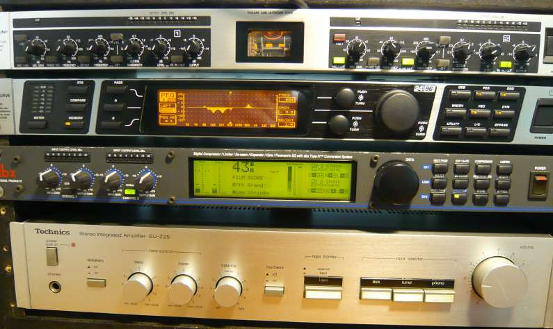 A key box that will never (??) be replaced is the "preamp". It's the top box in the photo above. The current one is the Behringer UltraGain 2200. It contains a tube ("GT" Electronics) preamp that produces a warm sound. The main advantage is a one stage parametric (boxed in red) EQ that allows full control of the mic's input signal and pre-processes any frequency from 20hz to 10Khz with "attenuation" or "gain". I use it to remove the heavier low-mid frequency range (150hz to 300hz) BEFORE it gets into the following stages. 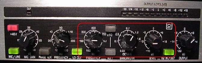 DEQ2496 Ultra Curve: The single replacement for the removed audio dynamics processors is the Behringer DEQ2496. It's the second box down from the top in the photo above. This is now my primary audio processor and I can say that it's a marvelous piece of DSP hardware and software. It tailors the audio dynamics not only based on "frequency" but also "level", so the EQ can change as a function of the input signal level! It can raise or lower the level of a specific frequency (or a band of frequencies) based on two parameters, "Gain" and "Threshold". Other parameters control the speed of how this is done. The standard usage of this device is to "lower" the gain above a certain level however many are not aware of another way of using the DEQ processor. That is to use it to "RAISE" the level rather than lower it. It has some advantages that would be hard to accomplish with a 'standard' audio dynamics equipment.  An example shows how this happens. Setting the "M-Gain" to a positive number (+10dB) means that as soon as the level drops
BELOW the "Threshold" (-23dB), the gain is increased by the amount of the M-Gain number, 10dB. When the input signal
level goes above the "Threshold", it is reduced by -10db to the "normal" value. The results are a louder audio almost
as if it was 'compressed' for low (soft) mic input levels.
An example shows how this happens. Setting the "M-Gain" to a positive number (+10dB) means that as soon as the level drops
BELOW the "Threshold" (-23dB), the gain is increased by the amount of the M-Gain number, 10dB. When the input signal
level goes above the "Threshold", it is reduced by -10db to the "normal" value. The results are a louder audio almost
as if it was 'compressed' for low (soft) mic input levels. Another way is take advantage of the DEQ's power is to use the shelving filter, "H12" (high-pass, 12dB/oct) or the "L12" (low-pass, 12dB/oct) rather than the bandpass filter, "BP". This results in a larger region of controlled gain audio.  In DEQ #1, the H12 shelving filter attenuates all frequencies above 100hz. In DEQ#3 as shown on the right, the L12
shelving filter results in all frequencies below 2000hz being attenuated when signal level crosses the threshold level.
This is a novel way of damping frequencies across a large frequency spectrum, 50hz to 2000hz. Check out the DEQ #1 for H12
and DEQ#3 for L12 usage in the "Current Audio Settings" table below. Try both, they might work for you!
In DEQ #1, the H12 shelving filter attenuates all frequencies above 100hz. In DEQ#3 as shown on the right, the L12
shelving filter results in all frequencies below 2000hz being attenuated when signal level crosses the threshold level.
This is a novel way of damping frequencies across a large frequency spectrum, 50hz to 2000hz. Check out the DEQ #1 for H12
and DEQ#3 for L12 usage in the "Current Audio Settings" table below. Try both, they might work for you! dbX Digital Dynamics Processor (DDP): My seccondary processor is the DDP. This is the third box down from the top in the above photo. This is an excellent DP and there's no plans to replace or remove it. It has the necessary audio dynamics functions such as Gate, Equalizer, Compressor and Limiter. Currently, just the Gate and Compressor are being used. The DDP is a DSP device and it has an extremely clean response with no audio coloration which is key for any good audio dynamics processor.
Current Dynamics Settings: The table above shows my current audio dynamics settings for easy reference. As you see, all settings are changed regularly b/c there are no "sacred" positions. These settings may need to be 'tweaked' abit for your particular radio and microphone but they should get you in the ballpark.
[Current Audio Settings for FT2000D: 10/5/11]
Note: The settings here are for use with the "Full_Rack_EQ". Make sure to turn OFF the radio's EQ settings. Check back regularly for the latest updates.
|

 The photo at the right shows the hookup that I use to sweep my audio rack. The inset photo shows the output signal into my laptop for
recording. A MP3, WAV files are generated as well as a SpectraPlus Pro chart.
The photo at the right shows the hookup that I use to sweep my audio rack. The inset photo shows the output signal into my laptop for
recording. A MP3, WAV files are generated as well as a SpectraPlus Pro chart.
|
Send me |