|
K6JRF's Page formerly W6FZC AL-1500 Timer/Overload Board Analysis |
|
This page details improvements that can be made to the Ameritron AL-1500 Timer/Overload (T/O) Board. By use of 5Spice
analysis, the ckt operation is detailed and recommendations are made. I switched from MSim's "PSpice" to a newer, more compact analysis program called "5Spice" written by Andresen Software. It features almost intuitive operation, has many powerful features and and allows the import of various Spice models so that the ckt can be simulated using the actual real world parts. Click here to see more information on this fine circuit analysis product. |
|
Timer Portion: As part of the AL-1500 Linear Amplifier's cktry, a Timer/Overload [T/O] serves to delay the application of the high-voltage until the tube's (8877) filament has been "warmed" for 3 minutes. A good thing indeed! The owners manual states: JRF comments/corrections in RED The AL-1500 has a circuit board mounted in the front panel side of the filter capacitor board that provides time delay to insure the cathode of the 3CX1500A7 has reached proper operating temperature before high voltage and RF drive power can be applied. This board also samples the peak grid current and removes drive if the grid current is excessive. The timer portion of this ckt board uses IC1A as a comparator to drive the complimentary darlington Q1 and Q2. When twelve, 12 volts is first applied to terminal "Y", diode D3 provides a regulated 5.1 volt reference. [Schematic and parts list shows a "5.6V zener", not "5.1V zener"]. Divider R8 and R7 reduces the reference voltage to 3.7 [4.0] volts. C9 [+/-20% variation] charges from current supplied by R9. After apx three (3) [2] minutes, the comparator output, pin 1, goes high. Q3's collector goes low and turns on Q2 and Q1. If the 12volt supply is momentarily interrupted, diode D1 discharges C9 through R6, R7 and R8. Any interruption of more than a few seconds requires a complete timing cycle to begin again. Eimac advises that the 8877 tube is thoroughly warmed before high-voltage and RF drive are introduced. The object here is to minimize filament "twisting" which can (and DOES) cause it to short to the cathode. Bad news when that happens! So how much delay time is enough?? A long time ago, I was told that 180 secs was a minimum 8877 warm up time and that if you question the Eimac engineers, they will tell you that 5 minutes is a better warmup time. In the current spec sheets, Eimac states a minimum of 90 secs. I personally like the longer time, b/c the tube is cold and the blower is blowing COLD air on a already cold tube. It would be nice to have the filaments heated a bit longer to 'counteract' the cool air being forced onto the tube. I have used 5 minutes in a previous linear amplifier but some might consider that to be excessive. However, I still believe the more time, within reason, is what should be used. So three - four minutes isn't too much IMO. The "overload" portion of the board is contained in IC1b and biased by resistors, R5 and R11. Input "W" is a voltage proportional to the amount of grid current via resistor, R3. When the voltage is greater than the bias on IC1b, pin 6, the opamp fires and turns on Q4 which energizes RLY 1 to force the tube into cutoff bias. Recycling the front panel OPR switch [from STBY to OPR] resets the overload portion of the circuit. The changes to the "timer" ckt do not effect the "overload" ckt. Timer/Overload Board Schematic: The schematic was copied from the user's manual and is shown here as received. 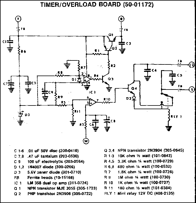 After the schematic has been translated into Spice, it appears as shown here;  Time/Overload Board Transient Analysis: The ckt works as follows: when the power (12V) is applied, capacitor C9 slowly charges ["RED" line] through R9 (1MEG) and reaches the trigger point of LM358 comparator ["GREEN" line]. When they equal each other the comparator fires ["BLUE" line] and turns on transistor Q3 which then fires Q2 and Q1. I've added the new parameter, "Rrelay" which represents the load for RLY1. The value chosen is taken from the relay's specs for its 1.4W power dissipation. The means that the range of coil resistance comes out to be apx 97 ohms. So now the ckt is required to produce at least 120ma of current to guarantee that the relay, RLY1 can be held energized. Subjecting the ckt to 5Spice analysis showed that the timing is short of three (3) minutes as stated in the manual. The chart shows that it times out in 2.12 minutes [127 secs] with R8= 680 ohms (stock ckt). My AL-1500 times out in 2.2 mins; another times out in 2.1 mins. The Rrelay current is plotted on the right side axis and shows that the required load current is available and that it switches without any delay. The ckt depends on the RC charging rate of R9, 1M ohm and C9, 100uf. Since there are not precision parts with tight tolerances, the time can vary as much as 20% in the extreme. So at best, the ckt is of marginal design as are many in the MFJ line of radio equipment.  Change Timer Board to 3 Minutes: Here's an expedient method that changes the timing to 3 minutes and it's very simple to accomplish. Change the bias divider resistor, R8 from 680 ohms to 330 ohms. Replace the 680 ohm resistor with a 330 ohms, 1% resistor or parallel another 680 ohm resistor with the existing one. That results in apx 340 ohms, a lttle higher in value but no significant change in the timing cycle.  This results in a timing cycle of 182 secs or 3 mins, 2 secs. I recommend using this method since it is very easy to locate the resistor and solder another across the terminals. Modify Timer Board: Since it was a rainy day, this would be a good time to open the AL1500 and replace the R8 resistor. Here's the results. 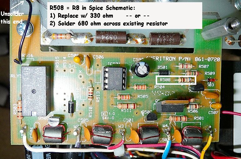 The T/O board [Ameritron PN: 861-0720] is located just below the HV-Diode Rectifier board and it's attached with two (2) screws so it's easy to modify without having to remove the board. The resistor in question is R508 and, as you can see, all of the board's components have the prefix of "50x". So R8 is really R508 as shown in the outline-box. There's enough "lead-length" available so that you can easily tack-solder a 680 ohm resistor across the existing one. Lightly scrape each end of the resistor's leads so that they are clean, then solder another 680 ohm resistor in parallel with it. Easy enough! I didn't have one so I had to replace with a 330 ohm from my parts box. For this operation, the board has to be "flipped" over. Unsolder the end of black wire that's soldered to the hv-rectifier board. After removing the screws that hold it, simply flip it over so the bottom side of the board is visible. Do not unsolder the five (5) wires connected to the ferrite bead terminals! Unsolder resistor R508 and replace with a 330 ohm resistor. The results are: 3.03 mins = 182 secs = 3 mins, 2 secs. 5Spice's analysis was right on!
|
| Send me |